


Assembly 43
MAN0943 (07/12/2011)
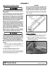
Do not position jackstands under wheels, axles, or
wheel supports. Components can rotate and cause
shredder to fall.
2. Consider the overall stability of the blocked unit.
Just placing jackstands underneath will not ensure
your safety.
The working surface must be level and solid to
support the weight on the jackstands. Make sure
jackstands are stable, both top and bottom. Make
sure shredder is approximately level.
3. With full shredder weight lowered onto jackstands,
test blocking stability before working underneath.
4. If shredder is attached to tractor when blocking, set
the brakes, remove key, and block shredder before
working underneath.
5. Securely block rear tractor wheels, in front and
behind. Tighten tractor lower 3-point arm anti-sway
mechanism to prevent side-to-side movement.
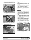
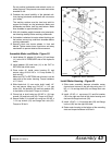
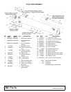
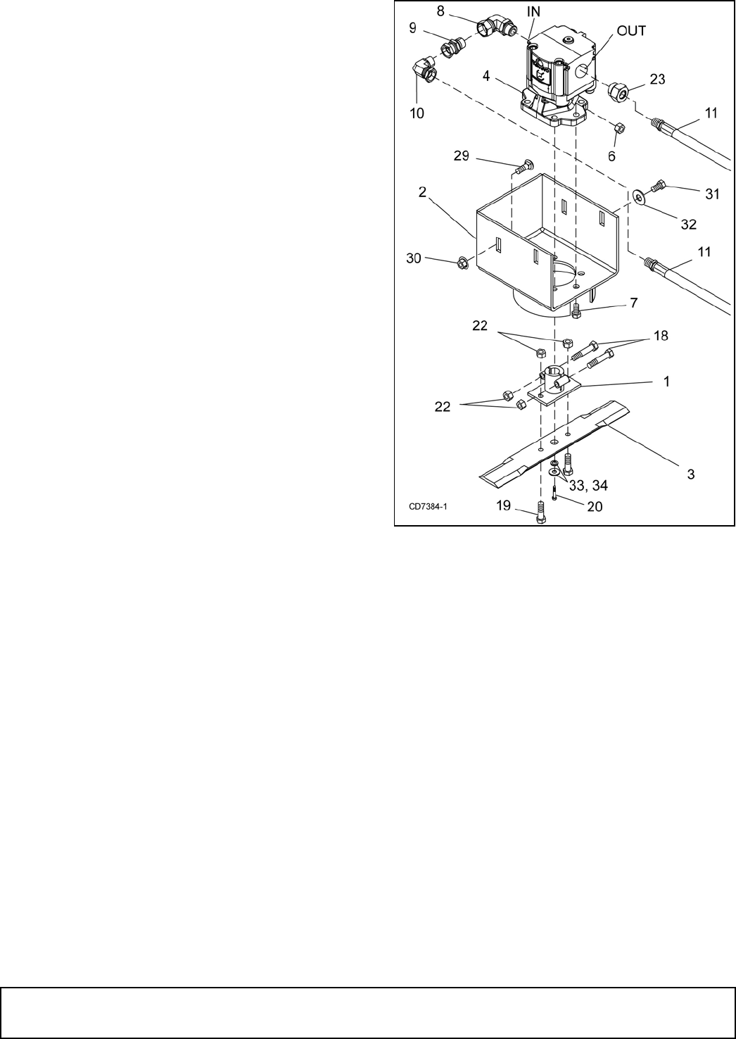
Assemble Motor and Blade - Figure 52
1. Install elbow (8), adapter (9), elbow (10) and hose
(11) to the IN or PRESSURE side of the hydraulic
motor.
2. Install adapter (23) and hose (11) to the OUT or
RETURN side of the motor.
3. Place motor (4) inside motor housing (2) and
secure using six 9/16 NC x 1-1/2 cap screws (7)
lock nuts (6).
Make sure OUT or RETRUN side of motor is on the
open side of the motor housing. Torque hardware
to 171 lbs-ft.
4. Slide blade hub (1) over motor shaft, install 1/4"
key and secure using one 5/16 NF x 1-1/2 cap
screw (20), flat washers (33) and lock washer (34)
in the bottom of the shaft. Torque to 19 lbs-ft.
5. Clamp hub to shaft using two 3/8 NC x 1-3/4 cap
screws (18) and lock nuts (22). Torque to 35 lbs-ft.
6. Secure blade (3) to blade hub using two 3/8 NC x
1-1/4 cap screws (19) and flange lock nuts (22).
Torque to 35 lbs-ft.
Figure 52. Motor Assembly
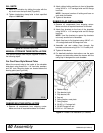
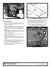
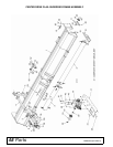
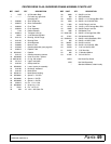
Install Motor Housing - Figure 53
1. Slide motor assembly between shredder center
channel and secure to the left side using two 1/2
NC x 1-1/4 carriage bolts (29) and flange lock nuts
(30).
2. Install 1/2 NC x 1 cap screw (31) and flat washer
(32) to the right rear hole of the motor housing and
secure with flange lock nuts (30).
3. Install 1/2 NC x 1-1/4 carriage bolt (29) and flange
lock nut (30) into the right front hole.
4. Raise motor housing to the bottom of the mounting
slots and torque hardware to 85 lbs-ft.