


TECHNICAL SUPPORT 1 800 908 0884
3
WARNING - Not following these instructions may cause severe injury or death to persons.
IMPORTANT SAFETY INFORMATIONIMPORTANT SAFETY INFORMATION
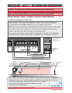
6. Controls intended for user activation must be located at least six feet (6’) away from any mov-
ing part of the gate and where the user is prevented from reaching over, under, around or
through the gate to operate the controls. Outdoor or easily accessible controls shall have a secu-
rity feature to prevent unauthorized use.
7. The Stop and/or Reset button must be located in the line-of-sight of the gate. Activation of the
reset control shall not cause the operator to start.
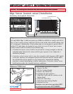
8. All warning signs and placards must be installed where visible in the area of the gate. A minimum
of two placards shall be installed. A placard is to be installed in the area of each side of the
gate and be visible to persons located on the side of the gate on which the placard is installed.
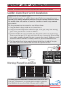
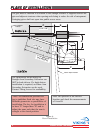
9.
For gate operators utilizing a non-contact sensor (Photo beam or like) in
accordance with section 31.1.1 of the UL325 standard:
a) See instructions on the placement of non-contact sensors for each Type of
application (refer to page 6),
b) Care shall be exercised to reduce the risk of nuisance tripping, such as when
a vehicle, trips the sensor while the gate is still moving, and
c) One or mor
e non-contact sensors shall be located where the risk of entrapment
or obstruction exists, such as the perimeter reachable by a moving gate or
barrier (refer to page 6).
d) Use only Omron E3K-R10K4 photoelectric eye to comply with UL325
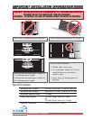
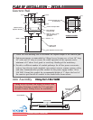
10.
For a gate operator utilizing a contact sensor (Edge sensor or like) in
accordance with section 31.1.1 of the UL325 standard:
a) One or more contact sensors shall be located where the risk of entrapment or
obstruction exists, such as at the leading edge, trailing edge, and post mounted
both inside and outside of a vehicular horizontal slide gate (r
efer to page 7).
b) One or more contact sensors shall be located at the bottom edge of a vehicular
vertical lift gate.
c) One or more contact sensors shall be located at the pinch point of a vehicular
vertical pivot gate.
d) A hardwired contact sensor shall be located and its wiring arranged so that the
communication
between the sensor and the gate operator is not subjected to
mechanical damage.
e) A wireless contact sensor such as one that transmits radio frequency (RF)
signals to the gate operator for entrapment pr
otection functions shall be
located where the transmission of the signals are not obstructed or impeded
by building structures, natural landscaping or similar obstruction. A wireless
contact sensor shall function under the intended end-use conditions.
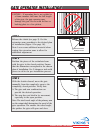
f) One or more contact sensors shall be located on the inside and outside leading
edge of a swing gate. Additionally, if the bottom edge of a swing gate is greater
than 6 inches (152 mm) above the gr
ound at any point in its ar
c of travel, one
or more contact sensors shall be located on the bottom edge (refer to page 7).
g) One or more contact sensors shall be located at the bottom
edge of a vertical barrier (arm).
h) Use only Miller Edge Model MGR20 or MGS20 edge sensor
to comply with UL325
IMPORTANT INSTALLATION INSTRUCTIONS Continued