


TECHNICAL SUPPORT 1 800 908 0884
6
IMPORTANT SAFETY INFORMATIONIMPORTANT SAFETY INFORMATION
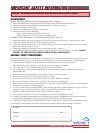
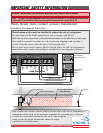
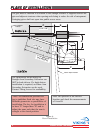
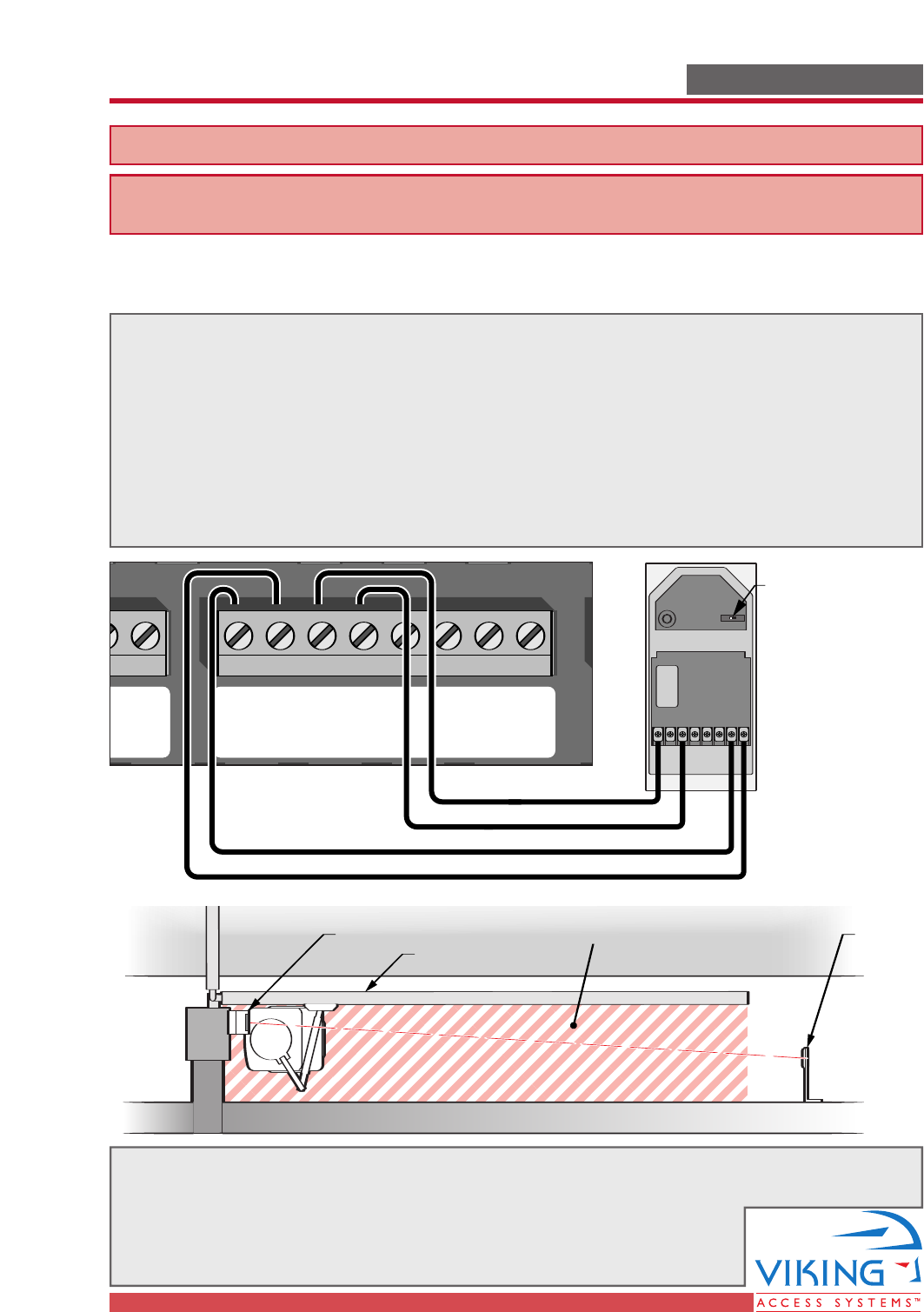
Gate in Open Position
Photo Beam Unit Reflector
Potential Entrapment
Area (Shaded)
Radio Station
Mag.
Lock
Mag. Lock
Safety ConnectorOpen CommandsGuard StationMaster/Slave
Brake
UL
Siren
Radio
Rec.
UL
Sensor
OPEN RIGHT
OPEN LEFT
Safety
Loop
Center
Loop
Obstruction
Sensor
Charger
Power
Low Battery
Motor Sensor
Hold Open
Timer
Stop
Overlap Delay
Close Open
Obstruction
Sensor
min.MAX
Overlap Delay
1.5
0
3
Radio Station
Loop Connector Open Commands Guard Station
Master/Slave
GND
Close
Stop
Open
GND
Close
Stop
Open
Gnd
Fire
Gnd
Strike
Gnd
Exit
Gnd
Center
Gnd
Reopen
Gnd
UL
Gnd
+28v
Gnd
Radio
Gnd
+28v
+28v
Mag.
Lock
Fail Safe/Secure
Mag. Lock
N.C.
COM
N.O.
Charger
Power
Low Battery
Motor Sensor
Hold Open
Timer
Stop
CloseOpen
LimitLimit
30sec
60secoff
1sec
Radio
Rec.
UL
Sensor
Safety
Loop
Center
Loop
Brake
UL
Siren
Obstruction
Sensor
min. MAX
Overlap
Delay
1.5
0
3
Mag.
Lock
Fail
Safe/Secure
Hold Open
Timer
Stop
Close
Open
30
60
Off
1
Radio
Rec.
UL
Sens
Safety
Loop
Center
Loop
Brake
Siren
11
(C1)(C1)
33
(NC1)(NC1)
24VDC24VDC
1
(C1)
3
(NC1)
24VDC
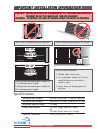
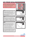
Turn Switch to
'Light On' Position
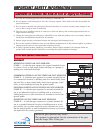
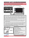
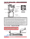
24 VDC Power Connections
24 VDC Power Connections
Omron Model
E3K-R10
Shown
Connection '3' (NC1)
Connection '1' (C1)
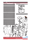
One or more non-contact sensors shall be located where the risk of entrapment or
obstruction exists, such as the perimeter reachable by a moving gate or barrier.
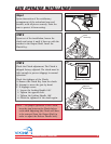
Consult the installation manual for the UL325 device (photo
beam or like) for detail information about the usage,
installation and maintenance.
W
ARNING - Not following these instructions may cause severe injury or death to persons.
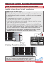
Photo Beam (non-contact sensor) Installation
Secondary Entrapment Protection
Photo beams or like must be installed to reduce the risk of entrapment.
Use only Omron E3K-R10K4 photoelectric eye to comply with UL325
Make the electrical connections of the photoelectric sensor as described here in this page.
Care shall be exercised to reduce the risk of nuisance tripping, such as when a
vehicle, trips the sensor while the gate is still moving, and
One or more non-contact sensors shall be located where the risk of entrapmentor
obstruction exists, such as the perimeter reachable by a moving gate or barrier.
NOTE - This type of installation DOES NOT reverse the gate all the way back to its limits when the photo-beam
is obstructed. This installation is only to protect against entrapment and to comply with UL325.