


TECHNICAL SUPPORT 1 800 908 0884
14 18
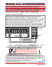
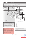
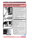
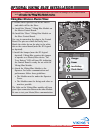
The Gate Operator requires a single phase AC
line to operate and charge the batteries.
1. Turn off the main switch or breaker for
the power line being used.
2. Move the selector switch on the Incoming
Voltage Selector to the proper position
(115 for 110 to 120VAC, 230 for 200 to 240VAC).
3. Connect the incoming power wires to the
terminals as shown in the illustration.
4. Turn on the main switch or breaker once
the installation is ready for final
adjustments.
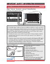
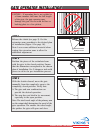
5.
To verify that there is AC power to the
system, check that the ‘Charger’ LED on the
Control Board is on.
ELECTRICAL INSTALLATIONELECTRICAL INSTALLATION
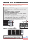
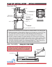
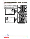
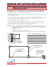
Tips for proper ground installation
A good ground in a gate operator
installation will minimize or prevent damage
to the operator cause by natural events such
as lightning strikes.
The following will provide a guideline for
proper grounding:
1. Use a ground rod to provide a ground
reference.
2. Consult your city code and be aware of
under-ground services in the site of the
gate operator to prevent inconveniences.
3. Use always a single bonding point for
grounding.
4. All ground wires must be as short and as
thick as possible.
5. Prevent unnecessary turns or loops in all
ground wires.
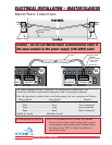
Caution – Do not connect the power harness to the board
until the installation is ready for verification.
To
Transformer
Neutral
Power Ground
115V/220V
Power Switch
Earth Ground
Hot
3A FUSE
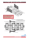
Part # VAEMI
Ground Rod
Earth Ground
Radio Station
Mag.
Lock
Mag. Lock
Safety ConnectorOpen CommandsGuard StationMaster/Slave
B
rake
UL
Siren
Radio
Rec.
UL
Sensor
OPEN RIGHT
24V BAT 24VAC
OPEN LEFT
Safety
Loop
Center
Loop
Obstruction
Sensor
Charger
Power
Low Battery
Motor Sensor
Hold Open
Timer
Stop
Overlap Delay
Close Open
Obstruction
Sensor
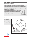
min. MAX
Overlap
Delay
1.5
0
3
Radio StationLoop ConnectorOpen CommandsGuard StationMaster/Slave
GND
Close
Stop
Open
GND
Close
Stop
Open
Gnd
Fire
Gnd
Strike
Gnd
Exit
Gnd
Center
Gnd
Reopen
Gnd
UL
Gnd
+28v
Gnd
Radio
Gnd
+28v
+28v
Mag.
Lock
F
ail
Safe/Secure
MAG. LOCK
N.C.
COM
N.O.
Charger
Power
Low Battery
Check Motor
Hold Open
Timer
Stop
Close
Open
30
60
Off
1
Radio
Rec.
UL
Sens
Reopen
Loop
Center
Loop
Brake
Siren
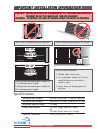
JP3
C35 C36
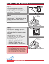
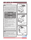
Power Harness
White
Green
Red
Black
Auxiliary Power Connection.
See page 27 for further details.