


TECHNICAL SUPPORT 1 800 908 0884
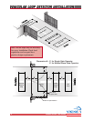
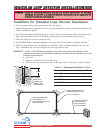
19
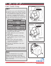
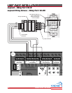
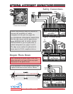
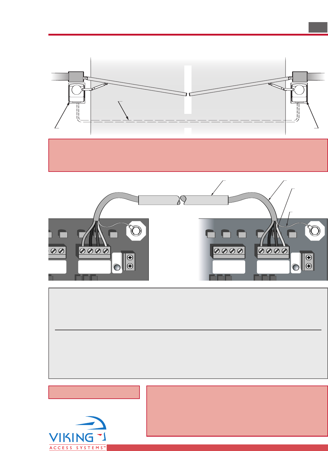
The control board provides a connector for master/slave connectivity. This
connector will allow synchronized operation with a second gate operator.
Wire the operators as shown above and interconnect the two operators as follows:
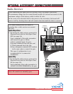
Master Board Slave Board Purpose
GND . . . . . . . . . . . . . . . . . . . .GND Reference
Close . . . . . . . . . . . . . . . . . . .Close Close Command
Stop . . . . . . . . . . . . . . . . . . . .Stop Stop Command
Open . . . . . . . . . . . . . . . . . . .Open Open Command
Shield (to Earth) Shield (to Earth)
Master/Slave Connections
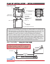
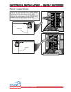
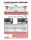
ELECTRICAL INSTALLATION – MASTER/SLAVEELECTRICAL INSTALLATION – MASTER/SLAVE
Inside
Outside
Slave UnitMaster Unit
Interconnecting
Conduit
Guard StationMaster/Slave
UL
Siren
Guard StationMaster/Slave
UL
Siren
Guard Station Master/Slave
GND
Close
Stop
Open
GND
Close
Stop
Open
UL
Siren
Guard Station Master/Slave
GND
Close
Stop
Open
GND
Close
Stop
Open
UL
Siren
Shielded Cable
NOTE:
Use 16 Gauge
Wire for runs
up to 100'
Conduit
Shield Wire
Caution – Do not run Master/Slave communication cable in
the same conduit as the power supply (120-220V) cable.
Note: It is recommended to connect all external
devices and set timer and overlap delay control
on the master unit. Ensure Slave Control Board
has timer set to ‘OFF’ to allow the Master to
control the timer.
For Overlap Delay see page 29.