


TECHNICAL SUPPORT 1 800 908 0884
11
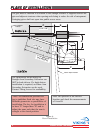
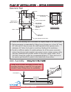
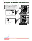
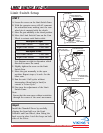
PLAN OF INSTALLATION – DETAILSPLAN OF INSTALLATION – DETAILS
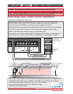
Drill for a 1/2" x 3-1/2"
Red Head Anchor
(4) Places
23-1/4"
11"
2.5"
2.5"
30"
7-5/8"
2-7/16"
10"
3-1/4"
6" Minimum
20"
12"
Conduit Location
Center of Output Shaft
Recommended Area
for Conduit(s)
Gate Operator
Concrete Pad
Gate Operator Concrete Pad
Operator Cover
Grade Level
See Note 2
Operator Chassis
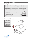
1. Follow the local building code to determine the required depth of the concrete pad.
2. Pad measurements recommended by Viking Access Systems are at least 20” long,
20” wide and 30” deep to ensure the stable operation of the operator, and a
minimum of 6” above level grade to avoid any flooding of the machinery.
4. Provide a sufficient number of conduit pathways for all low power accessories
such as loop detector leads, maglock, non-contact sensors, contact sensors, safety
and other commands.Also provide conduit for the power supply (either 110 or
220 VAC). Extend the conduit the recommended height of 1” above the level of
the concrete pad. Install all conduit in the shaded area shown above.
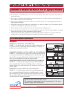
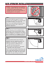
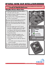
Secondary Extension
Dimension E
on Page 10
Dimension D
on Page 10
Primary Extension
Pivot Bracket
Arm Assembly Viking Part # VA-F1ARM
Concrete Pad
Viking Access Systems can supply an Elbow Arm
Secondary Extension to make the T-21 unit back-
drivable. Contact Viking Access for availability.