TECHNICAL SUPPORT 1 800 908 0884
34 31
OPTIONAL VIKING BLUE INSTALLATIONOPTIONAL VIKING BLUE INSTALLATION
Radio StationSafety ConnectorOpen CommandsGuard StationMaster/Slave
Brake
UL
Siren
OPEN RIGHT
24V BAT 24VAC
OPEN LEFT
Hold Open
Timer
StopClose Open
Obstruction
Sensor
min. MAX
Overlap
Delay
1.5
0
3
Radio StationLoop ConnectorOpen CommandsGuard StationMaster/Slave
GND
Close
Stop
Open
GND
Close
Stop
Open
Gnd
Fire
Gnd
Strike
Gnd
Exit
Gnd
Center
Gnd
Reopen
Gnd
UL
Gnd
+28v
Gnd
Radio
Gnd
+28v
+28v
Mag.
Lock
Fail
Safe/Secure
Charger
Power
Low Battery
Check Motor
Hold Open
Timer
Stop
Close
Open
30
60
Off
1
Radio
Rec.
UL
Sens
Reopen
Loop
Center
Loop
Brake
Siren
JP3
C35 C36
1. Insert CD into host computer
2. Install MS ActiveSync (check your
computer, it may already be installed to
communicate with a PDA or smart phone.
3. Install Viking Blue software
Select Install Viking-Blue for PC (to have the
computer to communicate with the Operator)
Select Install Viking-Blue for PDA (to have
the PDA to communicate with the Operator)
WARNING: If this PDA is a new device, turn off
all options when syncing with the computer.
For either installation, follow the steps in the
user manual.
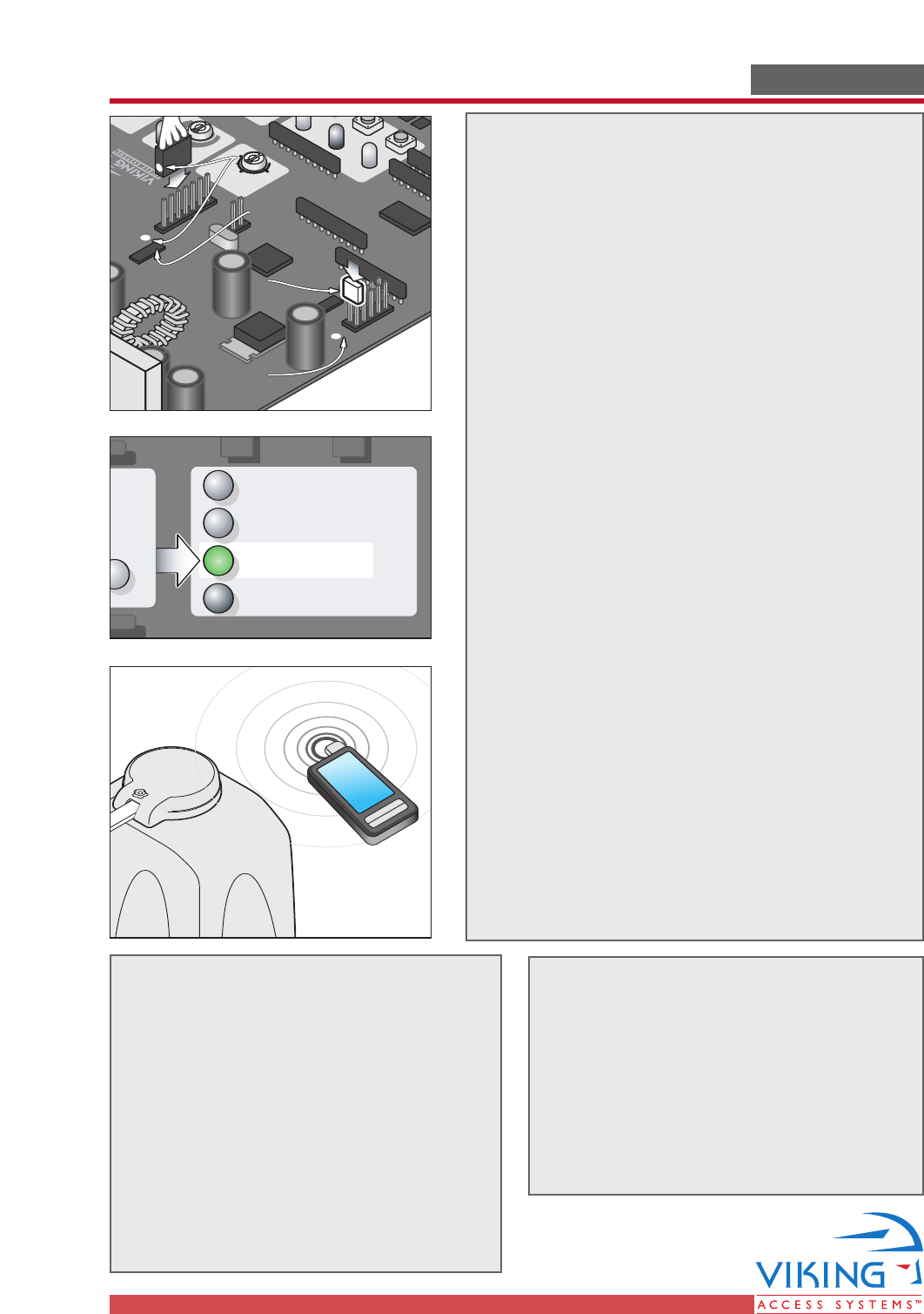
4. Plug the Viking Blue Module into the Viking
Gate Operator Control Board.
WARNING: Connecting the plug backwards can
result in damage to the Control Board and
will render the Viking Blue Module useless.
Use care in connecting the plug to the Control
Board. The pins are small and easily bent.
Match the white dot on the plug to the white
dot on the control board (near the JP2 legend
as depicted).
5. Install the Jumper (near the JP3 legend
depicted). Viking-Blue requires this jumper
to operate. The “Low Battery” LED will turn
ON, indicating the Control Board is ready for
use with the Viking-Blue Module.
6. Open Viking Blue software on the chosen
device.
If you are using the computer:
• Hold the computer near the Gate
Operator.
• Run the application by clicking the
icon on the desktop.
• Select “Setting” in the top right of the
screen.
If you are using a PDA:
• Hold the PDA near the Gate Operator.
• Select “Start” and “Programs”
.
• Click the Viking-Blue Application.
• Select “Connection” on the toolbar.
• Click “Search” (looking for available
Viking devices).
• Select the Operator you want to
communicate with.
• Click “Connect” to start communication.
The Light on the Viking-Blue module
will turn green upon connection to the
Computer or PDA.
Follow the steps in the user manual.
Radio Station
Op
en Comma
nds
Guard Stat
ion
Master/Slave
OPEN RIGHT
24V BAT
24V
AC
OPEN LEFT
Charger
Power
Low Battery
Radio Station
Loop Connec
t
or
Op
en Comma
nds
Guard Stat
ion
Master/Slave
GN
D
Clo
se
Sto
p
Op
en
GN
D
Clo
se
Sto
p
Op
en
Gn
d
Fire
Gn
d
Strike
Gn
d
E
xit
Gn
d
Cen
ter
Gn
d
R
eo
p
en
Gn
d
UL
Gn
d
+2
8
v
Gn
d
R
a
d
io
Gn
d
+2
8
v
+2
8
v
Mag.
L
ock
Fail
Safe/Secure
MAG. LOCK
N.C.
COM
N.O
.
Charger
Power
Low Battery
Chec
k Motor
30
60
O
ff
1
Radio
Rec.
UL
Sens
Reopen
L
oop
B
ra
k
e
Si
ren
JP3
C35
C36
JP2
Match upMatch up
White DotsWhite Dots
Match up
White Dots
InstallInstall
JumperJumper
Install
Jumper
JP3JP3JP3
JP2JP2JP2


