


TECHNICAL SUPPORT 1 800 908 0884
37
TROUBLESHOOTINGTROUBLESHOOTING
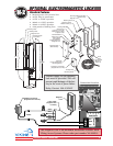
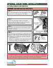
Check the incoming high
voltage power supply.
Check the proper selection of
power supply (120/220 VAC).
Refer to page 14.
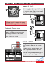
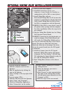
Verify the EMI board by
reading high voltage across the
(4) blue and red wires at the
terminal block connections.
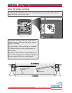
Gate opens after few second delay
Set the overlap delay trim pot
to 0. Refer to page 30.
Note: Overlap trim pot is
normally recommended to use
in overlapping gates. Refer to
page 30.
F-1 unit runs slower than normal
Set the overlap delay trim pot
to 0. Refer to page 30.
Note: Overlap trim pot is
normally recommended to use
in overlapping gates. Refer to
page 30.
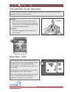
Gate opens. Closes or stops on its own
Ensure that the key for manual
release is in the lock position.
Refer to page 7.
Make sure that the ‘Charger’
LED is on, indicating that there
is AC power.
Check that your wires from
your accessories are:
a) Not shorting together
b) Not shorting a power line
c) Not shorting to metal or
earth ground.
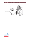
‘Charger’ LED off. Gate does not run - alarm sounds upon any input command
Check the 4 Amp fuse on the
control board.
Check the 3 Amp fuse on the
EMI board. Refer to page 14.
Make sure the incoming AC
line is properly connected.
Refer to page 14.
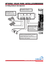
Battery voltage reads zero or very low
Ensure the batteries are connected as follows:
a) Left battery - Black terminal connected to the black wire from the harness (jacketed wire)
b) Left battery - Red terminal connected to the red wire from fuse holder
c) Right battery - Black terminal connected to the red wire from fuse holder
d) Right battery - Red terminal connected to the red wire from the harness (jack
eted wire)