


TECHNICAL SUPPORT 1 800 908 0884
7
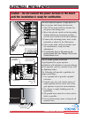
WARNING - Not following these instructions may cause severe injury or death to persons.
IMPORTANT SAFETY INFORMATIONIMPORTANT SAFETY INFORMATION
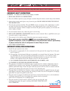
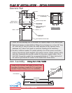
Edge Sensor (contact sensor) Installation
Secondary Entrapment Protection
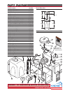
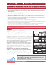
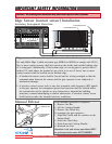
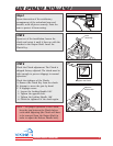
Manual Release
When manual operation is required:
1. Remove the Hat
2. Lift the Locking Handle.
3. Remove the Clutch Key
To reengage the gate operator:
1. Align the Clutch and the notches on the
Output Shaft.
2. Insert the Clutch Key.
3. Push down the Locking Handle.
4. Reattach the Hat.
Attention: Lock and release operations MUST
be performed with motor NOT RUNNING.
Remove Hat
Locking Handle
(in Unlocked
Position)
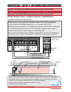
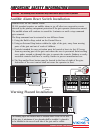
R
adio Station
Mag.
L
ock
Mag. Lock
S
afety Connector
O
pen Commands
G
uard Station
M
aster/Slave
Brake
U
L
S
iren
Radio
Rec.
UL
Sensor
OPEN RIGHT
OPEN LEFT
Safety
Loop
Center
Loop
Obstruction
Sensor
Charger
Power
Low Battery
Motor Sensor
Hold Open
T
imer
Stop
Overlap Delay
Close Open
O
bstruction
Sensor
min.MAX
Overlap Delay
1
.5
0
3
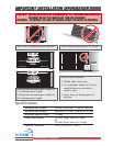
R
adio Station
L
oop Connector
O
pen Commands
G
uard Station
M
aster/Slave
GND
Close
Stop
Open
GND
Close
Stop
Open
Gnd
Fire
Gnd
Strike
Gnd
Exit
Gnd
Center
Gnd
Reopen
Gnd
UL
Gnd
+28v
Gnd
Radio
Gnd
+28v
+28v
Mag.
Lock
Fail Safe/Secure
Mag. Lock
N
.C.
COM
N.O.
Charger
Power
Low Battery
Motor Sensor
Hold Open
Timer
Stop
CloseOpen
LimitLimit
30sec
6
0secoff
1sec
Radio
Rec.
UL
Sensor
Safety
Loop
Center
Loop
Brake
U
L
S
iren
Obstruction
Sensor
min. MAX
Overlap
Delay
1.5
0
3
Mag.
Lock
Fail
Safe/Secure
Hold Open
Timer
Stop
Close
Open
30
60
Off
1
Radio
Rec.
UL
Sens
Safety
Loop
Center
Loop
Brake
Siren
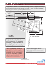
Edge sensor or like must be installed to reduce the risk of entrapment.
Use only Miller Edge 3-sided activation type MGR20 or MDS20 to comply with UL325
One or more contact sensors shall be located on the inside and outside leading edge
of a swing gate. Additionally, if the bottom edge of a swing gate is greater than 6
inches (152 mm) above the ground at any point in its arc of travel, one or more
contact sensors shall be located on the bottom edge.
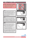
1. A hardwired contact sensor shall be located and its wiring arranged so that the
communication between the sensor and the gate operator is not subjected to
mechanical damage.
2. A wireless contact sensor such as one that transmits radio frequency (RF) signals
to the gate operator for entrapment protection functions shall be located where
the transmission of the signals are not obstructed or impeded by building
structures, natural landscaping or similar obstruction. A wireless contact sensor
shall function under the intended end-use conditions.
3
-Sided Edge Sensor
3
-Sided Edge Sensor