


TECHNICAL SUPPORT 1 800 908 0884
10
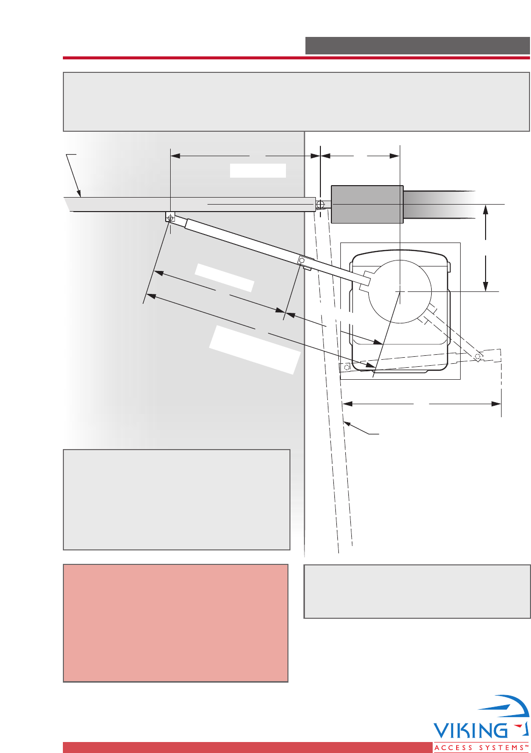
PLANS OF INSTALLATION PLANS OF INSTALLATION
BC
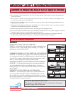
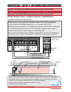
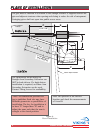
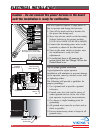
C = A + 12"
Inside
Outside
Gate in Closed
Position
D
D = (L x 0.4
)
E = (L x 0.6)
L = 87" Maximum
with Viking Arm
A
F
Gate in Open Position
E
L
The gate must be installed in a location so that enough clearance is supplied between the
gate and adjacent structures when opening and closing to reduce the risk of entrapment.
Swinging gates shall not open into public access areas.
*Note: The dimensions provided are
just a guideline. Each site may have
different geometries or possibilities of
installation. The key for installation is
to have "E" longer than "D" and to
adjust the arms such that the arm is
straight at the closed position.
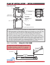
Figure A
Plan of Installation
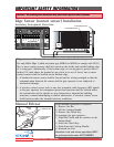
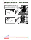
The installation shown using the
Straight Arm Secondary Extension can
NOT be back-driven. If a back-driven
installation is required, an Elbow Arm
Secondary Extension can be used.
Contact Viking Access for availability.
Place the operator at the desired
location and check the measurements
of A and B.