


Mfg P/N 98807 Rev 8, Page 9
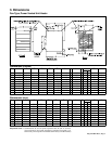
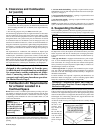
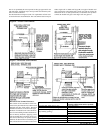
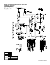
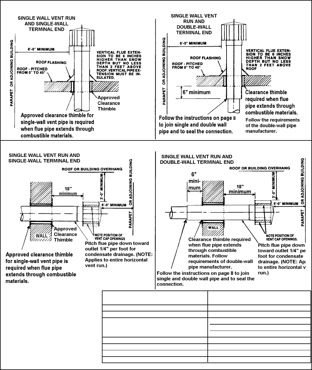
Figure 6 - Vertical Vent Terminals
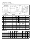
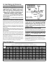
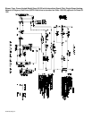
Figure 7 - Horizontal Vent Terminals
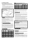
Horizontal Vent Terminal Clearances:
The location of the termination of the hori-
zontal vent system must be in accordance with
National Fuel Gas Code Z223.1. Required
minimum clearances are listed on the right.
Products of combustion can cause discolora-
tion of some building finishes and deteriora-
tion of masonry materials. Applying a clear
silicone sealant that is normally used to pro-
tect concrete driveways can protect masonry
materials. If discoloration is an esthetic prob-
lem, relocate the vent or install a vertical vent.
Structure Minimum Clearances for Vent Termination
Location (all directions unless specified)
Forced air inlet within 10 ft (3.1m) 3 ft (0.9m) above
Combustion air inlet of another appliance 6 ft (1.8m)
Door, window, or gravity air inlet 4 ft (1.2m) horizontally
(any building opening) 4 ft (1.2m) below
3 ft (0.9m) above
Electric meter, gas meter * and relief equipment 4 ft (1.2m) horizontally
Gas regulator * 3 ft (0.9m)
Adjoining building or parapet 6 ft (1.8m)
Grade (ground level) 7 ft (2.1m) above
*Do not terminate the vent directly above a gas meter or service regulator.
turer is not permitted; the vent cap must be the type approved for use
with this heater. A different style vent cap could cause nuisance prob-
lems or unsafe conditions.
See the illustrations in Figures 6 and 7 for requirements of both verti-
cal and horizontal vent termination. The vent terminal section may be
either single-wall or double-wall (Type B) vent pipe. If double-wall
pipe is used in the vent terminal with a single-wall vent run, follow the
instructions in No. 4, Vent System Joints, to attach the vent cap and to
connect the double-wall pipe to the single-wall vent pipe run.