


Mfg P/N 98807 Rev 8, Page 11
Before attempting to measure or adjust manifold gas pressure,
the inlet (supply) pressure must be within the specified range for
the gas being used both when the heater is in operation and on
standby. Incorrect inlet pressure could cause excessive manifold
gas pressure immediately or at some future time.
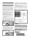
Instructions to Check Manifold Pressure:
1) With the manual valve (on the combination valve) positioned
to prevent flow to the main burners, connect a manometer to
the 1/8" pipe outlet pressure tap in the valve. NOTE: A ma-
nometer (fluid-filled gauge) is recommended rather than a
spring type gauge due to the difficulty of maintaining calibration of a
spring type gauge.
2) Open the valve and operate the heater. Measure the gas pressure to the
manifold. Normally adjustments should not be necessary to the factory
preset regulator.
If adjustment is necessary, set pressure to correct settings by turning the regu-
lator screw IN (clockwise) to increase pressure. Turn regulator screw OUT
(counterclockwise) to decrease pressure.
Consult the valve manufacturer's literature provided with the heater for more
detailed information.
11. Electrical Supply and Connections
All electrical wiring and connections, including electrical ground-
ing MUST be made in accordance with the National Electric
Code ANSI/NFPA No. 70 (latest edition) or, in Canada, the Ca-
nadian Electrical Code, Part I-C.S.A. Standard C22.1. In addi-
tion, the installer should be aware of any local ordinances or gas
company requirements that might apply.
Check the rating plate on the heater for the supply voltage and
current requirements. A separate line voltage supply with fused
disconnect switch should be run directly from the main electri-
cal panel to the heater. All external wiring must be within ap-
proved conduit and have a minimum temperature rise of 60
o
C.
Conduit from the disconnect switch must be run so as not to
interfere with the service panels of the heater.
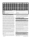
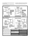
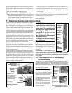
The electrical supply connects at the top back of the heater in the
left corner (left when facing the back of the heater). A threaded
hole is provided for a standard 1/2" electrical fitting.
The wiring access panel is easily removed for field connections.
Consult the wiring diagram supplied with your heater. Replace
the panel after the wiring connections are made.
If the heater has field-installed options that require electrical con-
nections, consult the instruction sheet and wiring diagram sup-
plied in the option package.
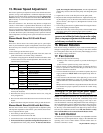
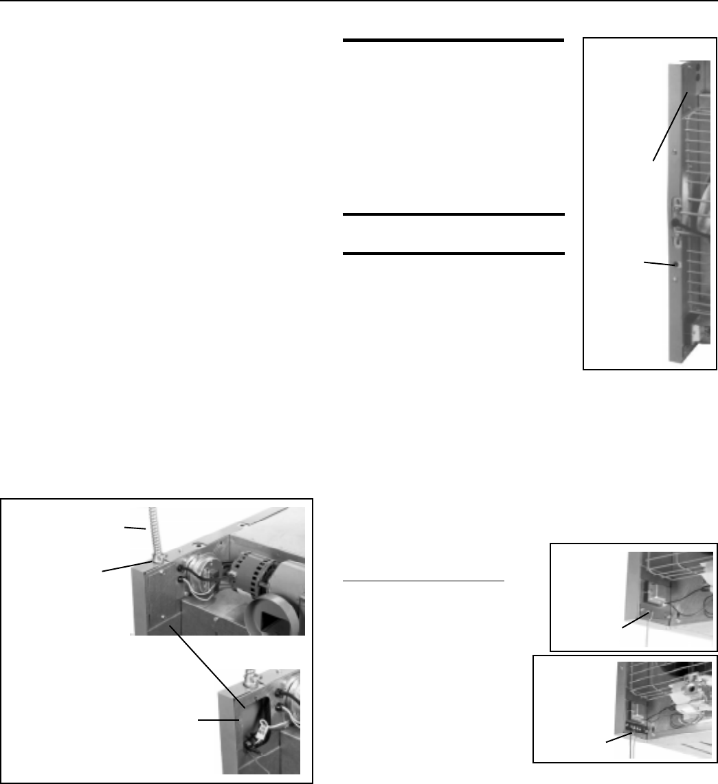
A fan-type heater may be equipped with a built-in fused discon-
nect switch (Option AI-1). If the heater is equipped with a built-
in disconnect switch, a two-position toggle (on/off) switch is
located near the electrical supply access panel (See Figures 9A
and 9B). This switch may be used to disconnect the power when
servicing the heater other than in the supply junction box.
Specific wiring diagrams that include standard and factory-in-
stalled options are included with the heater. Check the wiring
diagram to identify optional equipment.
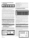
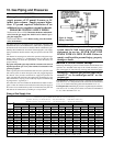
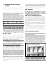
Figure 10 -
Two Screw
Terminal
Connector
Strip for
24-volt
Wiring
Figure 9A - Electrical
Connections
Remove
Access
Panel to
make
connections
WARNINGS: On a heater with
a unit disconnect switch (Option
AI-1), if the power is turned off
at the switch, the supply lead in
the electrical supply junction
box (Figure 9A) remains
energized. If service is to be
done in the supply junction box,
turn off the power at the remote
disconnect switch.
If you turn off the power supply,
turn off the gas.
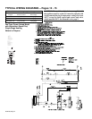
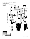
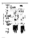
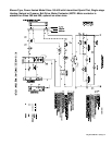
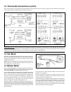
The operating sequence of the heater can be
found on the heater wiring diagram and is pub-
lished in Paragraph 24, Check Installation and
Start-Up. Typical wiring diagrams are on the
next four pages, showing standard single-
stage heating with spark pilot with and with-
out lockout.
CAUTION: If any of the original wire as
supplied with the appliance must be replaced, it must be replaced with
wiring material having a temperature rating of at least 105
o
C, except for
limit control and sensor lead wires which must be 150
o
C. See Hazard
Levels, page 2.
12. Thermostat and Thermostat
Connections
A thermostat is not standard equipment but is an installation requirement.
Use either an optional thermostat available with the heater or a field-supplied
thermostat. Install according to the thermostat manufacturer's instructions.
Make sure that the heat anticipator setting on the thermostat is in accordance
with the amperage value noted on the
wiring diagram of your heater.
Terminal Strip Connections - The
standard heater is equipped with a two-
screw terminal connector strip (See Fig-
ure 10) for easy connection to the low
voltage controls (24V). When factory-
installed options require two-stage
thermostat control, the heater is
equipped with a SP-ST relay and a
four-screw terminal connector strip
(See Figure 11).
If your heater requires field instal-
lation of the four-screw terminal
strip and the relay, follow the in-
structions packaged with the relay
or thermostat option.
If equipped
with unit-
mounted
disconnect
switch, on/
off toggle
switch is
near access
panel to
electrical
supply
junction
box.
Circuit
breaker
button for
Option AI-1
unit-
mounted
disconnect
switch
Threaded
Hole for
Standard 1/2"
Fitting
Figure 11 -
Four Screw
Terminal
Connector
Strip for 24-
Volt Wiring
Figure 9B
(Paragraph 12 continued on page 16.)
Field Wiring
from Disconnect
in Conduit
Note: Fan-type
heaters with optional
built-in disconnect
switch, have an on/off
switch located near
the electrical supply
access panel.