


Form 436, Page 26
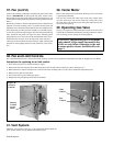
37. Fan (cont'd)
Position the assembly on the heater. Attach the fan guard at the center
mounts. (IMPORTANT: If replacing the fan guard, use the screws
that held the original fan guard. These specially designed screws will
cut through the coating on the fan guard to provide a ground for the fan
motor.)
Rotate the fan blade to check for adequate clearance. If adjustment is
required, loosen the mounting screws, re-position the fan guard, and
tighten the screws. Rotate the fan blade and re-check for adequate clear-
ance. Repeat this procedure until the assembly is positioned properly.
5. If necessary, drill the required upper and lower fan guard mounting
holes. Attach the fan guard at all upper and lower mounting points
using either the screws removed or field-installed sheet metal screws.
6. Reconnect the fan motor wires and replace the outer side panel.
7. Restore power to the heater and turn on the gas. Light, following the
instructions on the lighting instruction plate. Check for proper opera-
tion.
38. Venter Motor
Remove dirt and grease from the motor housing. Power venter motor
is permanently lubricated.
The vent relay controls the venter motor. If the relay contacts fail to
close the venter motor will not run. If the relay contacts fail to open,
the venter motor will not shut off, preventing the combustion air pres-
sure switch from opening.
39. Operating Gas Valve
The gas valve requires no field maintenance except careful removal of
external dirt accumulation and checking of wiring connections. Instruc-
tions for testing pressure settings are in Paragraph 10.
CAUTION: The operating valve is the prime
safety shutoff. All gas supply lines must be free
of dirt or scale before connecting to the unit
to ensure positive closure. See Hazard Levels,
page 2.
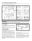
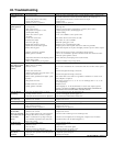
40. Fan and Limit Controls
If it is determined that the fan or limit control needs replacing, use only factory-authorized replacement parts that are designed for your heater.
Instructions for replacing fan or limit control:
1. Turn off the electric power and shut off the gas supply.
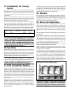
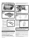
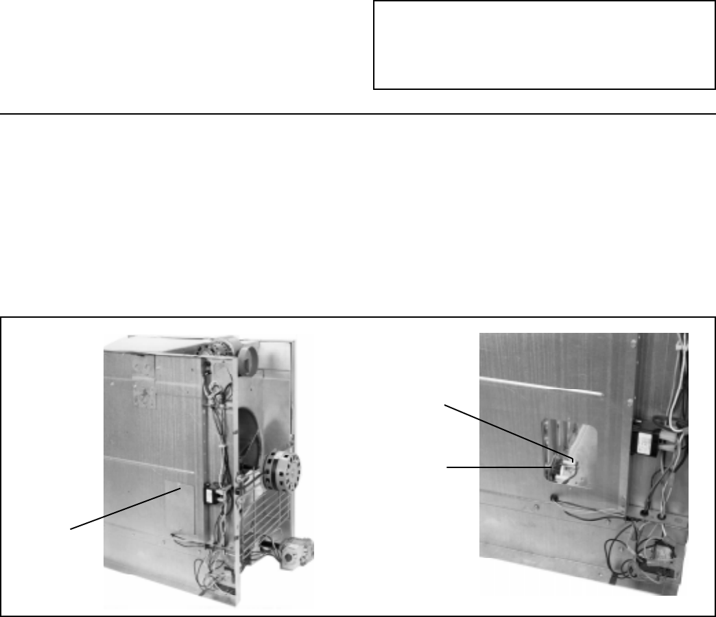
2. Remove the outer left side panel (left when facing the back of the unit). Remove the access panel. (See Figure 34.)
3. Remove defective controls and install new controls in the same mounting holes. Use only factory-authorized replacement parts.
4. Replace access panel and side panel.
5. Turn on the electric power and the gas supply.
6. Relight following the lighting instructions on the heater.
Figure 34 -
Access to
Controls
41. Vent System
Check the vent system at least once a year. Inspection should include all
joints, seams, and the vent cap. Replace any defective parts.
Remove
Control
Access
Panel
Fan
Control
Limit
Control