


Form 436, Page 6
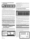
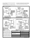
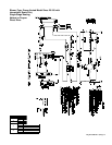
Figure 1 -
Confined Space: A
space whose volume is
less than 50 cubic feet
per 1000 BTUH of the
installed appliance
input rating
Add total BTUH of all appliances in the confined space and divide by
figures below for square inch free area size of each (top and bottom)
opening.
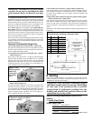
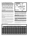
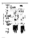
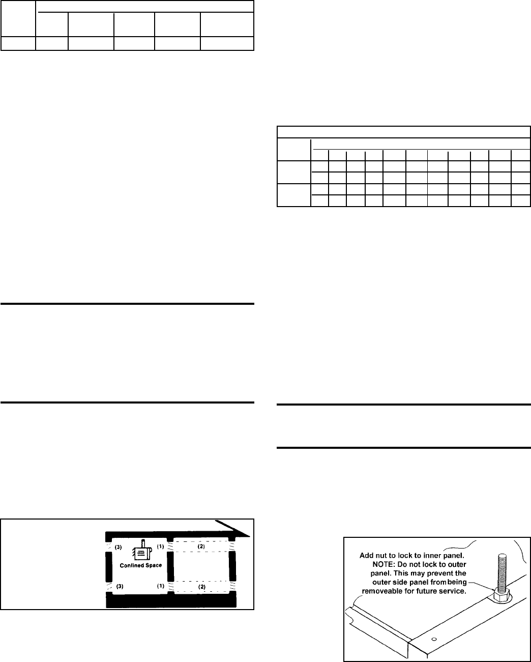
Figure 2 -
Suspension
* When supplied with optional downturn nozzle, bottom clearance is
42"(1067mm). For service purposes, on standard units, bottom clear-
ance exceeding minimum (12" or 305mm) is not required but may
be desirable.
** For servicing purposes only, rear must remain full open.
All fuel-burning equipment must be supplied with the air that enters
into the combustion process and is then vented to the outdoors. Suffi-
cient air must enter the equipment location to replace that exhausted
through the heater vent system. In the past, the infiltration of outside
air assumed in heat loss calculations (one air change per hour) was
assumed to be sufficient. However, current construction methods uti-
lizing more insulation, vapor barriers, tighter fitting and gasketed doors
and windows or weather-stripping, and mechanical exhaust fans may
now require the introduction of outside air through wall openings or
ducts.
The requirements for combustion and ventilation air depend upon
whether the unit is located in a confined or unconfined space. An "un-
confined space" is defined as a space whose volume is not less than 50
cubic feet per 1000 BTUH of the installed appliance. Under all condi-
tions, enough air must be provided to ensure there will not be a nega-
tive pressure condition within the equipment room or space. For spe-
cific requirements for confined space installation, see Paragraph 7.
WARNING: These power-vented unit heaters are
designed to take combustion air from the space
in which the unit is installed and are not designed
for connection to outside combustion air intake
ducts. Connecting outside air ducts voids the
warranty and could cause hazardous operation.
See Hazard Levels, Page 2.
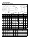
7. Combustion Air Requirements
for a Heater Located in a
Confined Space
Do not install a unit in a confined space without providing wall open-
ings leading to and from the space. Provide openings near the floor
and ceiling for ventilation and air for combustion as shown in Figure
1, depending on the combustion air source as noted in Items 1, 2, and
3 below the illustration.
6. Clearances and Combustion
Air (cont'd)
1. Air from inside the building -- openings 1 square inch free area per
1000 BTUH. Never less than 100 square inches free area for each open-
ing. See (1) in Figure 1.
2. Air from outside through duct -- openings 1 square inch free area
per 2000 BTUH. See (2) in Figure 1.
3. Air direct from outside -- openings 1 square inch free area per 4000
BTUH. See (3) in Figure 1.
NOTE: For further details on supplying combustion air to a confined
space, see the National Fuel Gas Code ANSI Z223.1a (latest edition ).
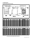
8. Suspending the Heater
Before suspending the heater, check the supporting structure to be used
to verify that it has sufficient load-carrying capacity to support the weight
of the unit.
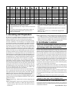
Net Weight (lbs and kg)
Model Size
Type 25 50 75 100 125 165 200 250 300 400
Fan lbs 76 83 92 101 132 154 175 209 226 281
kg 34 38 42 46 60 70 79 95 103 127
Blower lbs 97 104 118 130 180 206 240 278 301 395
kg 44 47 54 59 82 93 109 126 137 179
Model Required Clearances (inches and mm)
Size Top Flue Sides Bottom Rear
Collector
25-400 6"(152) 6"(152) 18"(457) 12"(305) * 24" (610)**
NOTE: If the installation includes an optional stepdown transformer
kit (Option CF or CG), the stepdown transformer bracket is part of the
heater suspension and must be installed prior to hanging the heater.
Follow the instructions on the installation sheet included with the op-
tion kit.
A fan-type unit heater is equipped with standard two-point suspen-
sion. A 3/8-16 threaded hanger bracket assembly is located on each
side of the heater. If a fan-type unit has been ordered with optional,
factory-installed, four-point suspension (Option BJ6), it will have two
threaded hanger brackets on each side.
A blower-type heater is equipped with standard four-point suspen-
sion. Two 3/8-16 threaded hanger bracket assemblies are located on
each side of the unit. Each hanger bracket assembly is designed for
threaded rod attachment.
For both "standard" and "optional" suspension point dimensions, see
Dimension Tables in Paragraph 3. (Note: If installing Option CK19
hanger kit, suspension points change; see Figure 4B.)
WARNING: Suspend the heater only from the
threaded hanger brackets. Do not suspend from
the heater side panel.
When the heater is lifted for suspension, the bottom must be protected.
If the wooden crate bottom has been removed, the bottom of the heater
will have to be supported with plywood or other appropriately placed
material. If the bottom is not supported, the bottom access panel could
be damaged. Also, when lifting a blower unit, support the blower and
motor to prevent the unit from tipping.
All blower models have legs that support the blower assembly during
shipping. After
the unit is sus-
pended, these
legs should be
removed.
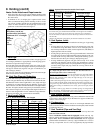
Be sure that the
threaded hanger
rods are locked
to the heater as
shown in Figure
2.