


Form 436, Page 24
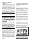
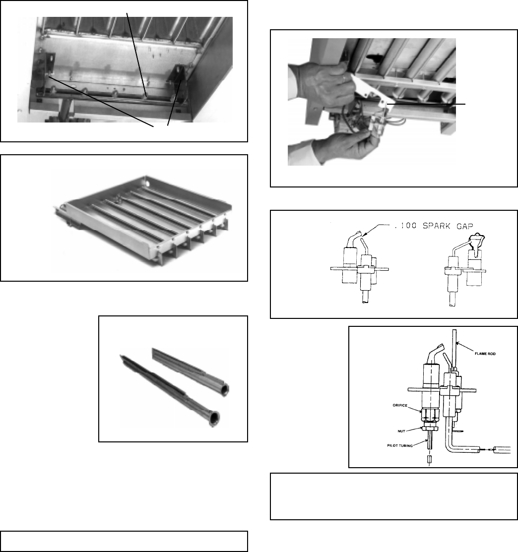
moval, Paragraph 32. The pilot can be removed to check the wiring,
the spark gap, or to remove the orifice for cleaning. When the pilot is
re-installed, be sure to include the pilot hole cover plate.
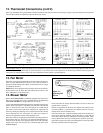
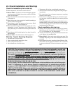
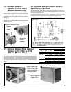
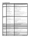
Spark gap must be maintained to .100". (See Figure 29.)
In the event the pilot
flame is short and/or
yellow, check the pi-
lot orifice for block-
age caused by lint or
dust accumulation.
Remove the pilot ori-
fice and clean with air
pressure. Check and
clean the aeration slot
in the pilot burner.
Figure 29 -
Pilot Burner
Spark Gap
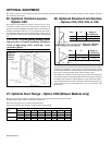
The ignition controller of the intermittent electronic ignition pilot sys-
tem is visibly located on the back of the heater. (See Figure 31.) Do not
attempt to disassemble the ignition controller. There are no field re-
placeable components in the control enclosure. However, each heating
season the lead wires should be checked for insulation deterioration
and good connections.
Proper operation of the electronic spark ignition system requires a
minimum flame signal of .2 microamps as measured by a
microampmeter.
For further information and check out procedure on the intermittent
electronic ignition pilot system, refer to the manufacturer's control op-
erating instructions supplied with the heater.
CAUTION: Due to high voltage on pilot spark
wire and pilot electrode, do not touch when
energized. See Hazard Levels, page 2.
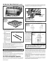
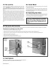
Figure 27 - Individual Burners
Figure 30 -
Pilot
Assembly
9. To remove the individual burners:
a. Remove the flash car-
ryover (one screw per
burner).
b. With the burner rack
upside down, remove
the sheet metal screws
(located at the rear)
that retain the burner
holddown.
c. Lift the rear of the
burner upward slightly
and pull back, remov-
ing the individual
burners.
d. To replace individual burners, reverse the above procedure.
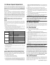
10. To replace the burner rack assembly and the bottom panel, re-
verse the above procedure (Steps 1-8).
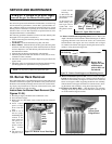
Individual burners may be cleaned using air pressure. Use an air nozzle
to blow out scale and dust accumulation from the burner ports. Alter-
nately, blow through burner ports and venturi.
Use a fine wire to dislodge any stubborn particles. Do not use anything
that might change the port size.
When any service is completed, be careful to reassemble correctly to
ensure that no unsafe conditions are created. When re-lighting, always
follow the lighting instructions on the heater.
33. Pilot and Ignition System
The pilot can be serviced by opening the bottom access panel of the
heater. Follow the first four steps of instructions for Burner Rack Re-
CAUTION: Eye protection is recommended.
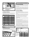
Figure 26 -
Burner Rack
Completely
Removed
Burner Assembly Support Brackets
Figure 25
32. Burner Rack Removal (cont'd)
Figure 28 - Pilot Removal
Pilot Hole
Cover
Plate
Burner Orifices