


Mfg P/N 98807 Rev 8, Page 5
4. Uncrating and Preparation
This unit was test operated and inspected at the factory prior to crat-
ing and was in operating condition. If the heater has incurred any
damage in shipment, file a claim with the transporting agency.
Check the rating plate for the gas specifications and electrical char-
acteristics of the heater to be sure that they are compatible with the
gas and electric supplies at the installation site. Read this booklet
and become familiar with the installation requirements of your par-
ticular heater. If you do not have knowledge of local requirements,
check with the local gas company or any other local agencies who
might have requirements concerning this installation. Before begin-
ning, make preparations for necessary supplies, tools, and manpower.
Check to see if there are any field-installed options that need to be
assembled to the heater prior to installation. Each of the option pack-
ages includes a list of components and step-by-step instructions. For
a brief description of optional hanger kits, refer to Paragraph 8. For a
brief explanation of other frequently specified field-installed options,
see Paragraphs 25-31. After becoming familiar with the instructions,
assemble and install the options that are required for your heater.
If the heater was ordered with a vent cap shipped with the heater
(Option BT2), packaging depends on the size of the heater. Sizes 25
and 50 have the vent cap mounted on a shipping tube that is attached
to the venter housing. Remove the vent cap; remove and discard the
shipping tube. Sizes 100, 165, 200, 250, 300 and 400 have the vent
cap attached directly to the venter housing. Size 125 is shipped with
the vent cap mounted on the crate near the gas valve. Remove the
vent cap for field installation at the vent terminal.
Unless the crate bottom has been removed for option installation,
leave it attached until after the heater has been suspended. If the
crate bottom has been removed, the bottom of the heater must be
supported with plywood or appropriately placed boards. Without
adequate support, the bottom access panel could be damaged.
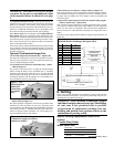
To protect the unit during shipping, the blower model has special
supports that must be removed before installation. Follow these in-
structions to remove:
oBlower Support Legs -- Remove the two blower support legs and
screws.
oMotor Shipping Block - Remove the wooden block located under
the motor bracket. Find the two rubber pads shipped in the in-
struction envelope. Place these pads on the ends of the motor
bracket bolts.
oMotor Shipping Plate -- Blower models that are equipped with motors
of 3/4 HP or less have a metal shipping plate attached between the
motor and the blower housing. Remove and discard the shipping plate.
Note: On units factory equipped with an optional belt guard, the belt
guard must be removed in order to reach the shipping plate.
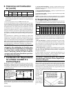
5. Unit Heater Location
CAUTION: Avoid installing a unit heater in extremely
drafty areas. Extreme drafts can shorten the life of the
heat exchanger and/or cause safety problems.
For best results, the heater should be placed with certain rules in mind. In
general, a unit should be located from 8 to 12 feet above the floor. Units
should always be arranged to blow toward or along exposed wall sur-
faces, if possible. Where two or more units are installed in the same room,
a general scheme of air circulation should be maintained for best results.
Suspended heaters are most effective when located as close to the work-
ing zone as possible, and this fact should be kept in mind when determin-
ing the mounting heights to be used. However, care should be exercised
to avoid directing the discharged air directly on the room occupants.
Partitions, columns, counters, or other obstructions should be taken into
consideration when locating the unit heater so that a minimum quantity
of airflow will be deflected by such obstacles.
When units are located in the center of the space to be heated, the air
should be discharged toward the exposed walls. In large areas, units should
be located to discharge air along exposed walls with extra units provided
to discharge air in toward the center of the area.
At those points where infiltration of cold air is excessive, such as at en-
trance doors and shipping doors, it is desirable to locate the unit so that it
will discharge directly toward the source of cold air from a distance of 15
to 20 feet.
Units should not be installed closer than 18 inches from any wall.
CAUTION: Do not locate the heater where it may be
exposed to water spray, rain or dripping water.
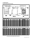
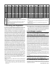
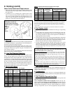
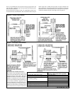
6. Clearances & Combustion Air
Units must be installed so that the following clearances are provided for
combustion air space, service and inspection, and for proper spacing from
combustible construction.
Use with 4-point suspension with blower cabinet.
Contactor is standard on Models 300 and 400; optional on other
sizes.
Contactor location with optional three phase motors on Sizes 50,
75, 100 and 125.
Deduct 6-5/8" on Sizes 50, 75, and 100 when equipped with
direct drive motor.
NOTES
When equipped with optional blower cabinet.
When equipped with optional duct flange.
Dimension includes a 3/4" flange on the rear of the blower
cabinet.
Use with 4-point suspension without blower cabinet. If
installing hanger kit Option CK19, suspension points
change; see Paragraph 8.
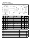
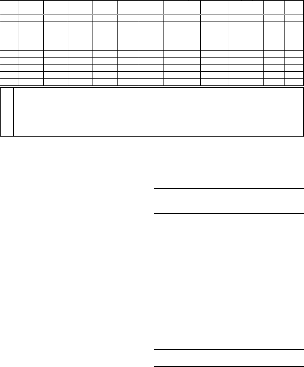
Size
MNPRST U W
XYZ
Hanger
25
94 532 481 133 273 214 375 157 793 249 76
50
94 532 481 133 273 214 375 157 793 249 76
75
69 532 481 133 324 214 375 157 793 265 76
100
44 532 481 133 375 214 375 157 793 265 76
125
34 532 481 133 521 214 521 157 908 294 67
165
72 659 641 184 445 291 521 202 932 297 117
200
34 659 641 184 521 291 521 202 932 297 117
250
150 1030 641 184 660 291 660 202 932 297 117
300
150 1030 641 184 660 291 660 202 932 297 91
400
172 1284 641 184 870 291 870 202 932 297 91