


Form 436, Page 8
9. Venting (cont'd)
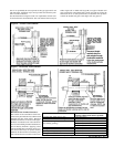
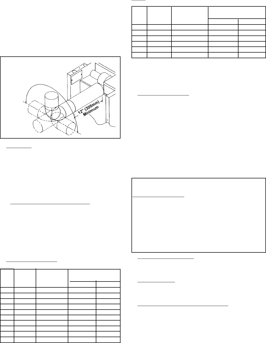
Venter Outlet Attachment Requirements:
• If the pipe used in the vent run is larger than the diameter of the
venter outlet (See Vent Length Table 2), make the transition at
the venter outlet.
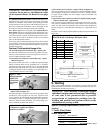
• A minimum of 12" of straight pipe is required at the venter
outlet (or transition fitting) before installing an elbow in the
vent system. An elbow should never be attached directly to the
venter. An elbow attached to the straight pipe can be in any
position at or above horizontal. See Figure 5.
2. Vent Pipe
If installed with a horizontal vent run, use either vent pipe approved
for a Category III heater or appropriately sealed 26-gauge galva-
nized steel or equivalent single-wall pipe.
If at least half of the equivalent length of the vent system is verti-
cal, vent pipe approved for a Category I heater may be used. Single-
wall pipe or double-wall (Type B) vent pipe are suitable for use
with a Category I heater.
Use only one of the flue pipe diameters listed in the Vent Length
Tables for the furnace size being installed.
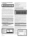
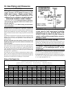
2A. Vent Pipe Diameter Reduction
If at least half of the equivalent length of the vent system is verti-
cal, the vent pipe diameter may be reduced one inch from the stan-
dard diameter listed in Vent Length Table 1. Only single-wall pipe
is suitable for use when reducing the pipe diameter. A taper-type
reducer must be used. The maximum allowable vent length remains
the same. If required, double wall pipe may be used at the terminal
end as shown in Figure 6. (Use the equivalent length for elbows as
shown in Vent Length Table 1 for the standard vent pipe diameter.
All elbows used in the vent system must be considered.)
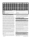
3. Vent Length Tables
Table 1: Maximum Permissible Vent Lengths
Vent Pipe Maximum Equivalent Straight
Model Diameter Vent Length* Length** - ft (m)
-" (mm) - ft (m) 90
o
Elbows 45
o
Elbows
25 4"(102) 30 ft (9.1 m) 3.5' (1 m) 1.8' (.5 m)
50 4"(102) 40 ft (12.2 m) 5' (1.5 m) 2.5' (.8 m)
75 4"(102) 50 ft (15.2 m) 7' (2.1 m) 3.5' (1.1 m)
100 4"(102) 50 ft (15.2 m) 7' (2.1 m) 3.5' (1.1 m)
125 5"(127) 50 ft (15.2 m) 5' (1.5 m) .5' (.8 m)
165 5"(127) 50 ft (15.2 m) 9' (2.7 m) 4.5' (1.4 m)
200 5"(127) 50 ft (15.2 m) 8' (2.4 m) 4.0' (1.2 m)
250 5"(127) 50 ft (15.2 m) 10' (3.0 m) 5' (1.5 m)
300 6"(152) 50 ft (15.2 m) 11' (3.4 m) 5.5' (1.7 m)
400 6"(152) 50 ft (15.2 m) 15' (4.6 m) 7.5' (2.3 m)
Figure 5 - Alternate Vent
Directions (vent in any
position above horizontal;
minimum of 12" of straight
pipe
required
before
an
elbow)
Table 2: Optional Maximum Permissible Vent Lengths
(Requires an increase in vent pipe diameter.)
Vent Pipe Maximum Equivalent Straight
Model Diameter Vent Length* Length** - ft (m)
- " (mm) - ft (m) 90
o
Elbows 45
o
Elbows
100 5" (127) 60 ft (18.3 m) 8' (2.4 m) 4.0' (1.2 m)
165 6" (152) 60 ft (18.3 m) 10' (3.0 m) 5.0' (1.5 m)
200 6" (152) 60 ft (18.3 m) 12' (3.7 m) 6.0' (1.8 m)
250 6" (152) 70 ft (21.3 m) 8' (2.4 m) 4.0' (1.2 m)
300 7" (178) 70 ft (21.3 m) 13' (4.0) 6.5' (2.0 m)
400 7" (178) 90 ft (27.4 m) 14' (4.3) 7.0' (2.1)
*Note 1: If the system contains all vertical pipe or a combination of horizontal
and vertical vent pipe, the Maximum Permissible Vent Length shown in Tables 1
and 2 may be increased one foot for each foot vertical rise up to a maximum
increase of 10 feet for model sizes 25 thru 100 and up to 20 feet for model sizes
125 thru 400.
**Reduce the maximum vent length by the amount indicated for each elbow.
4. Vent System Joints
Vent system joints depend on the installation and the type of pipe being
used.
• If using single wall, 26-gauge or heavier galvanized pipe, secure slip-
fit connections using sheet metal screws or rivets. Seal pipe joints ei-
ther with tape suitable for 550
o
F (such as Option FA1, P/N 98266) or
high-temperature silicone sealant.
• If using Category III vent pipe, follow pipe manufacturer's instructions
for joining pipe sections. When attaching Category III pipe to the ven-
ter outlet or the vent cap, make secure, sealed joints following a proce-
dure that best suits the style of Category III pipe being used.
• If using double-wall (Type B) vent pipe (allowed only if 1/2 of the
equivalent vent length is vertical), follow pipe manufacturer's instruc-
tions for joining pipe sections. For joining double-wall pipe to the ven-
ter outlet collar, single-wall pipe, and/or the vent cap, follow the in-
structions below.
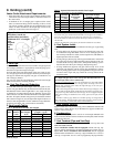
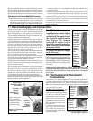
Instructions for attaching double-wall (Type B) vent pipe to the venter out-
let, a single-wall pipe run, or to the vent cap (use these instructions for ei-
ther full length double-wall or terminal only):
Hardware and Sealant Required: 3/4" long sheetmetal screws; and a tube of RTV
1) Look for the "flow" arrow on the vent pipe; attach according to the arrow.
Slide the pipe so that the venter outlet, the single-wall pipe, or the vent cap is
inside the double-wall pipe.
2) Drill a hole through the pipe into the outlet collar, the single-wall pipe, or the
vent cap. (Hole should be slightly smaller than the sheet metal screw being used.)
Using a 3/4" long sheet metal screw, attach the pipe. Do not overtighten. Repeat,
drilling and inserting two additional screws evenly spaced (120
o
apart) around
the pipe.
3) Use RTV to seal any gaps. If there is an annular opening, run a large bead of
RTV in the opening. The bead of RTV must be large enough to seal the opening,
but it is not necessary to fill the full volume of the annular area.
5. Vent System Support
Support lateral runs every six feet, using a non-combustible material such
as strap steel or chain. Do not rely on the heater for support of either hori-
zontal or vertical vent pipe
6. Condensation
Single wall vent pipe exposed to cold air or run through unheated areas
must be insulated. Where extreme conditions are anticipated, install a means
of condensate disposal.
7. Vent Terminal (Pipe and Vent Cap)
The vent system must be terminated with a suitable vent cap that is the
same size as the vent run.
Heaters installed in Canada must be equipped with the vent cap sup-
plied as optional equipment by the heater manufacturer (Option CC1 or
Option BT2). Heaters installed in the United States must be equipped
with the heater manufacturer's vent cap, a Type L Breidert Air-x-hauster
®
vent cap, or equivalent. Use of a vent cap supplied by the pipe manufac-