


Form 436, Page 10
10. Gas Piping and Pressures
WARNING
This appliance is equipped for a maximum gas
supply pressure of 1/2 pound, 8 ounces, or 14
inches water column. Supply pressure higher
than 1/2 pound requires installation of an
additional service regulator external to the unit.
PRESSURE TESTING SUPPLY PIPING
Test Pressures Above 1/2 PSI: Disconnect the heater and manual
valve from the gas supply line which is to be tested. Cap or
plug the supply line.
Test Pressures Below 1/2 PSI: Before testing, close the manual
valve on the heater.
All piping must be in accordance with requirements outlined in the
National Fuel Gas Code ANSI/Z223.1a (latest edition), published by
the American Gas Association or CAN/CGA-B149.1 and B149.2, pub-
lished by the Canadian Gas Association (See Paragraph 1). Gas supply
piping installation should conform with good practice and with local
codes.
Unit heaters for natural gas are orificed for operation with gas having a
heating value of 1000 (+ or - 50) BTUH per cubic ft. If the gas at the
installation does not meet this specification, consult the factory for
proper orificing.
Pipe joint compounds (pipe dope) shall be resistant to the action of
liquefied petroleum gas or any other chemical constituents of the
gas being supplied.
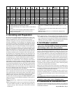
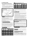
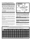
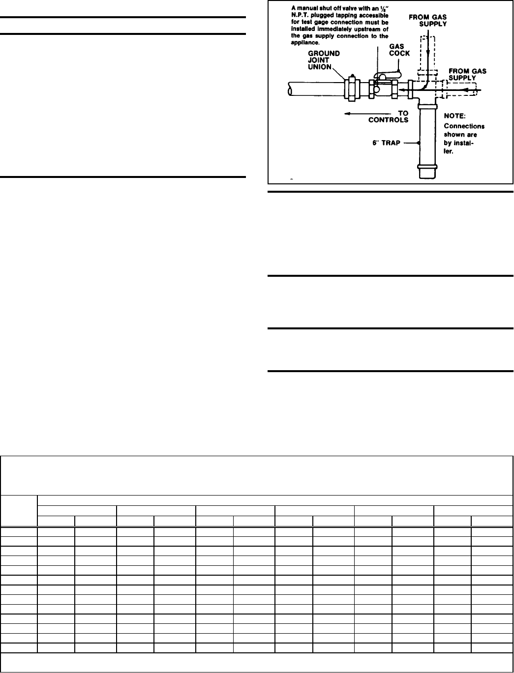
Install a ground joint union and manual shut-off valve upstream of the
unit control system, as shown in Figure 8. The 1/8" plugged tapping in
the shut-off valve provides connection for supply line pressure test
gauge. The National Fuel Gas Code requires the installation of a trap
with a minimum 3" drip leg. Local codes may require a minimum drip
leg longer than 3" (typically 6").
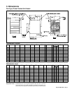
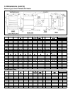
Gas connection sizes are included in the Dimensional Tables in Para-
graph 3. After all connections are made, disconnect the pilot supply at
the control valve and bleed the system of air. Reconnect the pilot line
and leak-test all connections by brushing on a soap solution.
Figure 8 - Supply
Piping Connection
WARNING: All components of a gas supply
system must be leak tested prior to placing
equipment in service. NEVER TEST FOR
LEAKS WITH AN OPEN FLAME. Failure to
comply could result in personal injury, property
damage or death.
Manifold or Orifice Pressure Settings
Measuring manifold gas pressure cannot be done until the heater is in
operation. It is included in the steps of the "Check-Test-Start" proce-
dure in Paragraph 24. The following warnings and instructions apply.
WARNING: Manifold gas pressure must never
exceed 3.5" w.c. for natural gas and 10" w.c. for
propane gas.
For Natural Gas: Manifold gas pressure is regulated by the combina-
tion valve to 3.5" w.c. Inlet pressure to the valve must be a minimum of
5" w.c. or as noted on the rating plate and a maximum of 14" w.c.
For Propane Gas: Manifold gas pressure is regulated by the combina-
tion valve to 10" w.c. Inlet pressure to the valve must be a minimum of
11" w.c. and a maximum of 14" w.c.
Sizing a Gas Supply Line
Capacity of Piping
Cubic Feet per Hour based on 0.3" w.c. Pressure Drop
Specific Gravity for Natural Gas -- 0.6 (Natural Gas -- 1000 BTU /Cubic Ft)
Specific Gravity for Propane Gas -- 1.6 (Propane Gas -- 2550 BTU/Cubic Ft)
Length Diameter of Pipe
of 1/2" 3/4" 1" 1-1/4" 1-1/2" 2"
Pipe Natural Propane Natural Propane Natural Propane Natural Propane Natural Propane Natural Propane
20' 92 56 190 116 350 214 730 445 1100 671 2100 1281
30' 73 45 152 93 285 174 590 360 890 543 1650 1007
40' 63 38 130 79 245 149 500 305 760 464 1450 885
50' 56 34 115 70 215 131 440 268 670 409 1270 775
60' 50 31 105 64 195 119 400 244 610 372 1105 674
70' 46 28 96 59 180 110 370 226 560 342 1050 641
80' 43 26 90 55 170 104 350 214 530 323 990 604
90' 40 24 84 51 160 98 320 195 490 299 930 567
100' 38 23 79 48 150 92 305 186 460 281 870 531
125' 34 21 72 44 130 79 275 168 410 250 780 476
150' 31 19 64 39 120 73 250 153 380 232 710 433
175' 28 17 59 36 110 67 225 137 350 214 650 397
200' 26 16 55 34 100 61 210 128 320 195 610 372
N ote: W hen sizing sup ply lines, consider p ossibilities of future exp ansion and increased requirements.
Refer to National Fuel Gas Code for additional information on line sizing.