


Form 436, Page 20
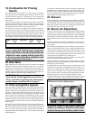
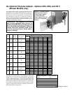
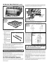
27. Optional Duct Flange - Option CD9 (Blower Models only)
OPTIONAL EQUIPMENT
This section contains a brief description of the more frequently specified field-installed options. All option packages include complete assembly
and installation instructions.
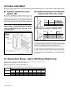
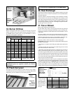
25. Optional Vertical Louvers -
Option CD1
The purpose of the addition of optional vertical louvers is to in-
crease the air pattern spread. The vertical louver assembly is de-
signed to be field assembled and installed. Refer to the instructions
packaged with Option CD1 for a list of components and step-by-
step installation instructions (Do not add optional vertical louvers to
a fan-type heater with downturn nozzle Option CD3. See Paragraph
26.)
CAUTION: To avoid getting burned, adjust
louvers prior to heater operation. If louvers
need re-adjusting after start-up, wear
protective gloves.
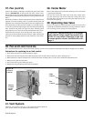
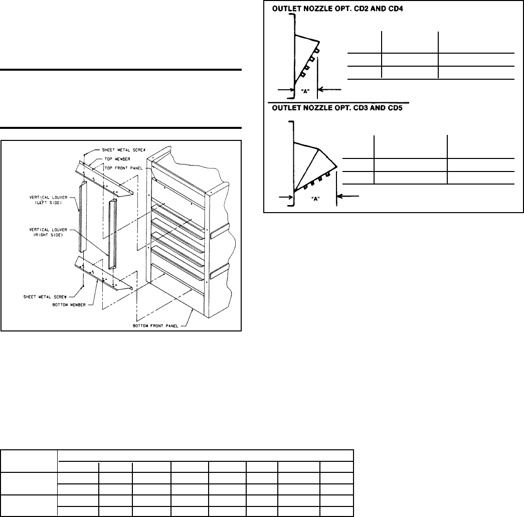
26. Optional Downturn Air Nozzles
- Options CD2, CD3, CD4, & CD5
Unit heaters may be specified with optional downturn air nozzles to direct
the discharge tempered air. The nozzles are shipped separately for field
assembly and installation. The horizontal louvers are removed from the
heater and re-installed into the outlet of the downturn nozzle.
The addition of a downturn nozzle requires four-point heater suspension.
Two hanger brackets are included with downturn nozzle options and must
be added to fan-type heaters with standard two-point suspension. Suspen-
sion point dimensions are found in Dimension Charts in Paragraph 3. On
fan-type heaters, do not install Option CD5 or use vertical louvers with
Option CD3.
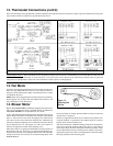
Figure 15 -
Optional
Vertical
Louvers
Sizes "A" Range of
Air Deflection
25-125 9" (229mm) 25
o
-65
o
165-400 13" (330mm) 25
o
-65
o
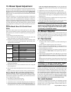
Figure 16 - Optional
Downturn Nozzles
Sizes "A" Range of
Air Deflection
25-125 16-1/2" (419mm) 50
o
-90
o
165-400 23-1/2" (597mm) 50
o
-90
o
Blower-type unit heaters may be connected to ductwork. The duct flange option is designed to adapt
the heater outlet (supply side) for connection to ductwork.
Ductwork connection sizes are shown in the chart below.
Follow the installation instructions included with the option package.
Model BE Duct Connection Sizes (inches and mm) with Optional Duct Flange
Size 25-50 75 100 125 165 200 250-300 400
Height 15-7/8 15-7/8 15-7/8 15-7/8 23-7/8 23-7/8 23-7/8 23-7/8
403 403 403 403 606 606 606 606
Width 10-3/4 12-3/4 14-3/4 20-1/2 17-1/2 20-1/2 26 34-1/4
273 324 375 521 445 521 660 870