


Mfg P/N 98807 Rev 8, Page 25
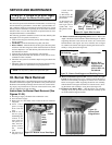
36. Heat Exchanger
The outside of the heat exchanger can be cleaned from the front of the
heater with an air hose and/or a brush. Remove all accumulated dust
and grease deposits.
The inner surfaces of the heat exchanger can be reached for cleaning
with the burner rack removed. (See Paragraph 32.) Cleaning can be
done with a long furnace brush or a heavy wire to which steel wool has
been attached. Brush up and down inside each heat exchanger tube
until all foreign material is removed. A flashlight is helpful in examin-
ing the upper section of the tube.
37. Fan or Blower
Remove dirt and grease from the motor.
On fan model units, remove dirt and grease from the fan guard and
blades. Use care when cleaning the fan blades to prevent causing mis-
alignment or imbalance. Check that the hub of the fan blades is secure
to the shaft.
On blower models, remove the grease and dirt from the blower hous-
ing and check the belt for wear and proper tension (See Paragraph 14.)
Lubricate if the motor has oil cups or grease fittings. The motor sup-
plied as standard has lifetime lubrication and sleeve bearings.
On blower models, check current draw to motor rating plate.
Fan Models: Follow these instructions for replacement of the fan guard,
fan motor or fan blades.
1. If the heater is installed, turn off the gas and disconnect the electric
power.
2. Remove the left outer side panel (left when facing the rear of the
unit). Disconnect the fan motor wires.
3. Depending on the date that the heater was manufactured, it will have
either a lower-half fan guard only, two-piece full fan guard, or a one-
piece full fan guard. If the unit has a two piece fan guard, remove the
tension mounted upper half fan guard and the four screws that hold the
lower half. If the unit has a one-piece fan guard, remove all of the
screws that retain the fan guard. Remove the assembled parts (the fan
guard, the motor and the fan blade).
4. Disassemble and replace whatever parts are needed and reassemble
using whatever part(s) are being replaced and the original parts. If the
fan guard is being replaced, it is important that the same hardware be
used for attaching the motor to the fan guard as was used with the
original guard. These screws are especially made to cut through the
coating on the fan guard to provide adequate grounding for the motor.
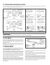
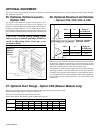
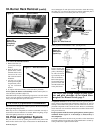
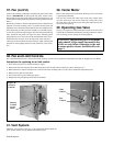
Figure 33 -
Proper Position
of the Fan
Blade on the
Motor Shaft
CAUTION: Eye protection is recommended.
Fan Hub
A
Fan
Motor
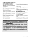
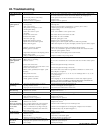
Figure 32 -
Burner
Rack Flash
Carryover
Flash
Carryover
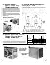
35. Flash Carryover
See Figure 32. The burner carryover system receives its gas supply
from the main burner ports. Check the carryover assembly and also the
main burner ports for cleanliness. Clean with air pressure.
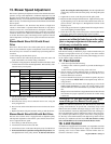
WARNING: Do not use this table for gas conversion.
Additional parts are required; contact your Reznor
Distributor.
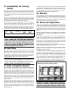
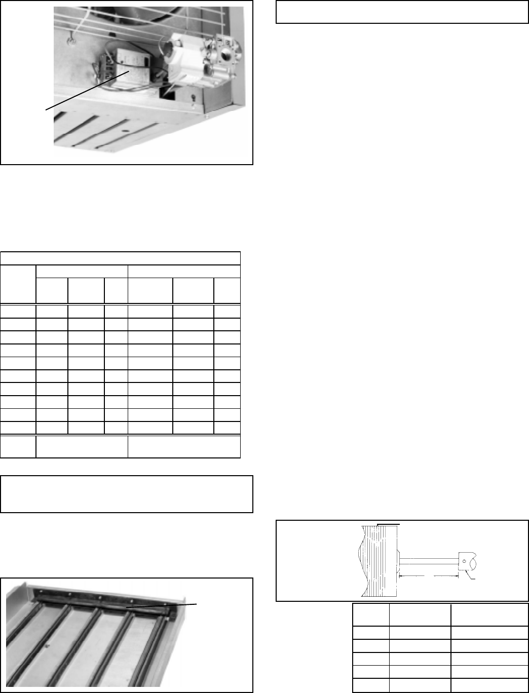
Figure 31
- Ignition
Controller
Location
Ignition
Controller
for Spark
Pilot
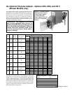
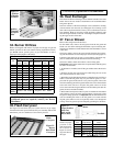
34. Burner Orifices
Heaters are shipped with orifices of proper size and type for gas and
altitude specified on the order. When ordering replacement orifices,
give BTUH content, specific gravity of gas, and altitude, as well as
model and serial number of the heater.
Be sure the fan
blade is in proper
position on the
shaft. Position the
fan as shown in
Figure 33 accord-
ing to the chart on
the right.
Model Set Screw “A” Hub to
Size Torque In-Lbs Motor
25 80 + or - 10 1-1/4" (32mm)
50 80 + or - 10 3/8"(10mm)
75 80 + or - 10 1/8" (3mm)
100-125 120 + or - 10 2-1/2" (64mm)
165-400 150 + or - 10 2-1/2" (64mm)
Main Burner Orifices (sea level)
Model Natural Gas Propane Gas
Size Drill
Size
Orifice
P/N
Qty Drill Size
Orifice
P/N
Qty
25 51 39650 2 60 95936 2
50 47 84853 3 1.2MM 63003 3
75 45 38678 4 1.3MM 64676 4
100 44 11833 5 55 11830 5
125 44 11833 6 55 11830 6
165 35 11831 5 1.65MM 96344 5
200 35 11831 6 1.65MM 96344 6
250 35 11831 8 1.65MM 96344 8
300 35 11831 9 1.65MM 96344 9
400 35 11831 12 1.65MM 96344 12
Pilot
Orifice
Natural - P/N 103034 Propane - P/N 98695