


Form 436, Page 18
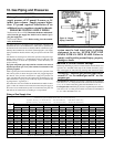
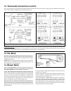
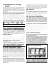
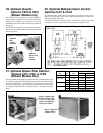
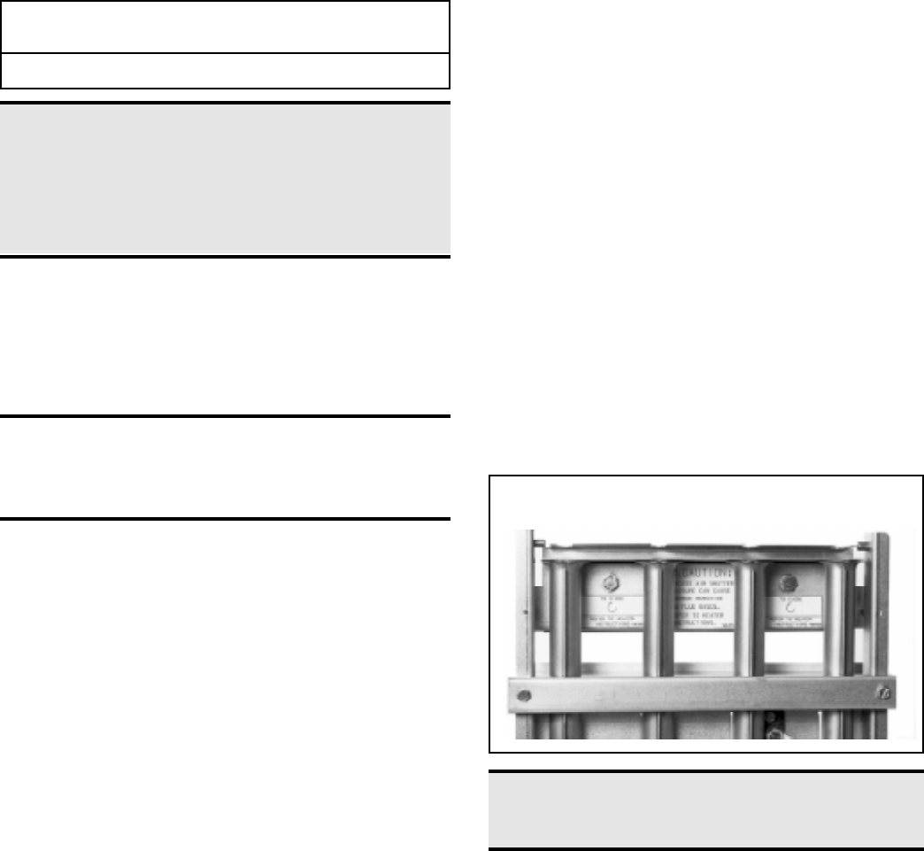
Figure 14 - Air Shutter Adjustment Screws -- Alternate
Turning Screws When Adjusting Shutter
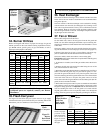
19. Combustion Air Proving
Switch
The combustion air proving switch is a pressure sensitive switch that
monitors air pressure to ensure that proper combustion air flow is avail-
able. The switch is a single pole - normally open - device which closes
when a decreasing pressure is sensed in the outlet duct of the flue gas
collection box.
On start-up when the heater is cold, the sensing pressure is at the most
negative level, and as the heater and flue system warm up, the sensing
pressure becomes less negative. After the system has reached equilib-
rium (about 20 minutes), the sensing pressure levels off.
If a restriction or excessive flue length or turns cause the sensing pres-
sure to become less than the switch setpoint, the pressure switch will
function to shut off the main burners. The main burners will remain off
until the system has cooled and/or the flue system resistance is reduced.
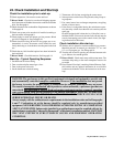
The Table on the right lists the approximate water column negative pres-
sure readings and switch setpoints for sea level operating conditions.
DANGER: Safe operation of this unit requires
proper venting flow. NEVER bypass combustion
air proving switch or attempt to operate the unit
without the venter running and the proper flow
in the vent system. Hazardous conditions could
result. See Hazard Levels, page 2.
20. Gas Valve
Main operating valve is powered by the 24-volt control circuit through
thermostat and safety controls. The main control valve is of the dia-
phragm type with magnetic pilot servo bleed operators, providing regu-
lated gas flow preset at the factory. The valve body also incorporates a
magnetic valve providing pilot gas control for the electronic ignitor sys-
tem and redundant or dual valve safety shutoff function.
WARNING: The operating valve is the prime
safety shutoff. All gas supply lines must be free of
dirt or scale before connecting the unit to ensure
positive closure. See Hazard Levels, page 2.
21. Pilot and Ignition System
These unit heaters are equipped with a spark ignited intermittent safety
pilot system that shuts off the pilot gas flow between heat cycles. In
addition, propane units are equipped with a spark pilot system that in-
corporates a lockout device that stops the gas flow to the pilot if the
pilot fails to light in 120 seconds. The spark pilot with 100% lockout
requires manual reset by interruption of the thermostat circuit. Propane
units require the lockout; natural gas units may be equipped with either
standard spark pilot or spark pilot with lockout (Option AH3). Refer to
the wiring diagram with your heater for pilot system identification and
proper wiring.
The ignition controller in the spark pilot system provides the high volt-
age spark to ignite the pilot gas and also acts as the flame safety device.
After ignition of the pilot gas, the control electronically senses the pilot
flame. (A separate solid metal probe in the pilot burner assembly is
employed for the flame sensing function. A low voltage electrical signal
is imposed on that metal probe which is electrically isolated from
ground. When the pilot flame impinges on the flame sensing probe,
the flame acts as a conduction path to ground. The pilot flame recti-
fies and completes the DC circuit. The ignition controller acknowl-
edges the flame and energizes the main gas valve.)
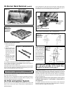
22. Burners
These unit heaters have individually formed steel burners with accu-
rately die-formed ports to give controlled flame stability without lift-
ing or flashback with either natural or propane gas. The burners are
lightweight and factory mounted in an assembly which permits them
to be removed as a unit for inspection or service.
23. Burner Air Adjustment
All sizes of these unit heaters that are equipped with standard alumi-
nized burners are designed to operate without burner air shutters when
fueled with either natural or propane gas. However, Sizes 165 through
400 equipped with optional stainless steel burners (Option AD2) re-
quire air shutters (Option AE1) when used with propane gas (Option
AA2).
Optional air shutters, either factory or field installed, are available for
any size model for use where unusual conditions cause excess pri-
mary aeration.
Before making any adjustments to the air shutters, allow the heater to
operate for about fifteen minutes. The air shutter adjustment screws
can be reached by opening the bottom panel. (Remove the two screws
located at the rear of the bottom panel and allow the panel to hinge
down from the front.) The adjustment screws for the air shutters are
visible at the rear of the burner rack . See Figure 14.
When making the adjustment, close the air shutters no more than is
necessary to eliminate the problem condition.
Observe the flame for yellow-tipping. A limited amount of yellow-
tipping is permissible for liquefied petroleum gases. Other fuels should
not display any yellow-tipping.
Two adjustment screws are used (See Figure 14). Rotating the screws
clockwise closes the shutters, reducing the primary air supply. Coun-
terclockwise rotation opens the shutters, increasing the primary air
supply. The two adjustment screws should be rotated alternately to
open or close the shutters. Attempting to gain adjustment by not alter-
nating between the two screws may cause the shutters to bind.
After proper adjustment has been completed, eliminating the problem
condition, close the bottom panel and replace the retaining screws.
Model Start-Up Equilibrium Set Point Set Point
Size Cold "OFF" "ON"
25-400 -1.0" w.c. -0.60" w.c. -0.47" w.c. -0.64"w.c.
DANGER: Failure to install and/or adjust air
shutters according to directions could cause
property damage, personal injury, and or death.