


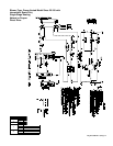
Mfg P/N 98807 Rev 8, Page 23
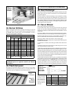
SERVICE AND MAINTENANCE
This unit will operate with a minimum of maintenance. To ensure long
life and satisfactory performance, a heater that is operated under nor-
mal conditions should be inspected and cleaned at the start of each
heating season. If the heater is operating in an area where an unusual
amount of dust or soot or other impurities are present in the air, more
frequent maintenance is recommended.
The following procedures should be carried out at least annually (See
Paragraphs 32-41 for specific instructions.):
1. Clean all dirt and grease from the primary and secondary combus-
tion air openings.
2. Fan Models - Clean the fan blade, fan guard, and motor.
3. Blower Models - Clean the blower, the belt guard, the inlet guard,
and motor of all dirt and grease. Check the blower belt for tension
and wear. Replace a worn belt that may fail before the next sched-
uled maintenance check.
4. Clean the heat exchanger both internally and externally.
5. Check the pilot burner and main burners for scale, dust, or lint ac-
cumulation. Clean as needed.
6. Check the vent system for soundness. Replace any parts that do not
appear sound.
7. Check the wiring for any damaged wire. Replace damaged wiring.
(See Paragraph 11 for replacement wiring requirements.)
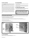
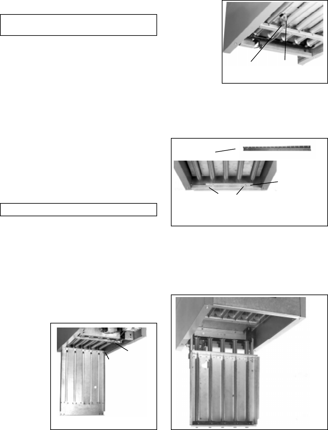
32. Burner Rack Removal
These unit heaters have a convenient bottom access panel. The pilot is
attainable with the bottom panel open. With the access panel removed,
the burner rack assembly will hinge down for removal. Use the follow-
ing step-by-step instructions for removal of the bottom access panel
and the complete burner rack assembly.
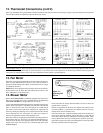
Instructions for Burner Rack Removal (See
Figures 21-24.)
1. Shut the gas supply off ahead of the combination valve.
2. Turn off electric supply.
3. Remove the two sheet metal screws located at the rear of the bot-
tom panel.
4. Allow bottom
panel to hinge
down from the
front.
5. Push in one of
the two spring-
loaded hinge pins
located at the
front of the bot-
tom panel (in-
side), and com-
pletely remove
the bottom
panel.
6. The bottom of
the pilot is now
visible. Do the
following:
(a) Disconnect the
pilot tubing from the
pilot burner.
(b) Disconnect the
flame sensing wire
and high tension
(spark) lead from
the ignition control-
ler.
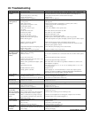
7A. Heaters manufactured beginning 8/91 (Serial No. Date Code
AQH) - The burner rack is indexed as illustrated in Figure 23. While
supporting the burner rack, remove the screws (two or three) that
hold the burner rack support. (For screw location, refer to Figure
23.) Remove the burner rack support allowing the burner rack as-
sembly to swing down (See Figure 24).
7B. Heaters manufactured prior to 8/91 (Serial No. Date Code AQH)
Loosen the sheet metal screws (two or three) located at the front of
the burner rack assembly. See Figures 23. These screws retain the
burner rack support. While supporting the burner rack assembly,
slide the burner rack support and remove it from the screws, allow-
ing the burner rack assembly to swing down (See Figure 24).
8. To Remove the Burner Rack -- With the burner rack assembly
"hanging" down, lift up on the rear and slide the assembly up and
out of the manifold support brackets.
WARNING: If you turn off the power supply,
turn off the gas. See Hazard Levels, page 2.
NOTE: Use only factory-authorized replacement parts.
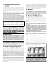
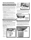
Figure 21- Bottom Access Panel Open
Push
hinge
pin to
remove
bottom
panel
Pilot
Location
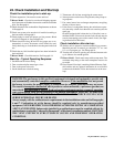
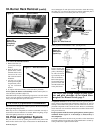
Figure 24 -
Burner Rack
Hinged Down
Pilot
Tubing
Flame
Sensor Lead
Figure 22 - Spark Pilot Location
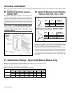
Burner Rack Support
with Indexing
Figure 23 - Burner Rack Support and Retaining Screws
Burner Rack
Support on units
manufactured
prior to 8/91 was
not indexed
Screws