


Mfg P/N 98807 Rev 8, Page 17
15. Blower Speed Adjustment
The blower speed may be adjusted to achieve the desired outlet tem-
perature, as long as the adjustment is within the temperature rise and
the static pressure limits shown on the heater rating plate. Direct drive
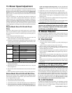
motors are factory set as indicated in the chart below. Belt drive mo-
tors are factory set at the mid-point between maximum and minimum
blower speeds.
If the duct resistance is low, the blower may deliver too high an air
volume; or if the heater is operated without ductwork, it may deliver
sufficient excess air to overload the motor, causing the overload pro-
tector to cycle the motor. Reducing the blower speed will correct these
conditions. If ductwork is added to an installation, it may be necessary
to increase the blower speed. Decreasing blower speed will increase
outlet temperature; increasing blower speed will decrease outlet tem-
perature.
Blower Model Sizes 25-100 with Direct
Drive
Direct drive blower motors have multi-speed taps for speed adjust-
ment. If your installation requires an adjustment of the blower speed,
the motor may be re-wired to an alternate tap by following these in-
structions.
1. Turn off the gas and the electric power.
2. Remove the left (left when facing the back of the unit) outer side
panel of the heater to reveal the wiring connections.
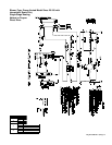
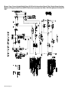
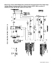
3. Consult the wiring diagram on the heater and follow the below chart
to choose the wire for the desired adjustment. The asterisk(*) indi-
cates the factory-wired speed.
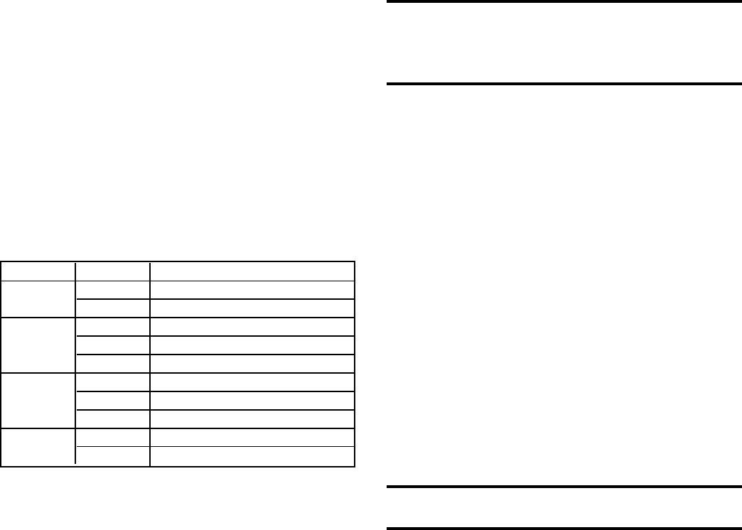
Model Size Speed Use these Two Motor Wires
25 *Medium *Blue and White
Low Red and White
50 *High *Black and White
Medium Blue and White
High Black and White
75 *Medium *Blue and White
Low Red and White
*High *Black and White
100 Medium Blue and White
Low Red and White
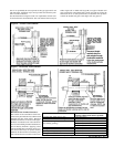
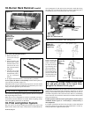
speed, increasing the outlet temperature, turn the adjustable half
of the pulley outward. One turn of the pulley will change the speed
8-10%.
5. Tighten the set screw on the flat portion of the pulley shaft.
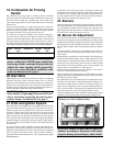
6. Replace the belt and adjust the belt tension. Adjust tension by turn-
ing the adjusting screw on the motor base until the belt can be de-
pressed 1/2-3/4". (See Figure 13.) Re-tighten the lock nut on the
adjusting screw.
7. Turn on the gas and electric. Light the heater following the instruc-
tions on the lighting instruction plate.
8. Check the motor amps with an amp meter. The maximum motor
amp rating on the motor nameplate must not be exceeded.
CAUTION: An external duct system static
pressure not within the limits shown on the rating
plate or improper adjustment of the motor pulley
or belt may overload the motor.
16. Blower Rotation
Each blower housing is marked for proper rotation. Rotation may be
changed on single-phase motors by re-wiring in the motor terminal
box. Three-phase motors may be reversed by interchanging two wires
on the 3-phase supply connections.
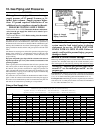
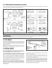
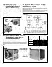
17. Fan Control
1. A fan control provides the following:
(a) Delay of fan or blower operation to prevent the discharge of
cold air.
(b) Fan or blower operation as long as the unit is hot.
2. The fan control provides additional safety by keeping the fan or
blower in operation in the event that the gas valve fails to close
when the thermostat is satisfied.
3. To be sure that the fan or blower can continue to operate, the power
supply to the heater MUST NOT be interrupted except when ser-
vicing the unit.
4. If the customer wants the heater off at night, the gas valve circuit
SHOULD BE OPENED by a single pole switch wired in series
with the thermostat. Some thermostats are provided with this fea-
ture.
Multiple units controlled from a single thermostat are shut off in the
same manner. For proper operation, be sure the fan control wiring
is observed.
WARNING: If you turn off the power supply,
turn off the gas. See Hazard Levels, page 2.
NOTE: Low ambient temperatures (less than 40
o
F) may cause false
cycling of the fan/blower. To prevent this, a time delay relay can be
added to the unit (available with single-stage gas valve only) to acti-
vate the fan/blower electrically independent of the heat exchanger or
the room temperature. The low ambient fan control relay can be fac-
tory installed; Option BF8 will appear on the heater wiring diagram.
Or, the relay can be field installed; order Option CQ3 (P/N 112779).
This relay is in addition to the fan control The fan control is a safety
device and should never be removed from the heater circuit.
18. Limit Control
All models are equipped with an automatic, non-adjustable reset limit
control that acts to interrupt the electric supply to the redundant main
operating valve in case of motor failure or lack of airflow due to re-
strictions at the inlet or outlet.
4. Cut the crimped cap from the end of the wire that you intend to use
and strip the insulation.
5. Disconnect the factory-wired connection and re-wire, using the
newly stripped wire.
6. Put a wire nut on the end of the blower motor wire that was discon-
nected.
7. Replace the heater side panel and turn on the gas and the electric.
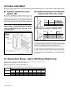
Blower Model Sizes 50-400 with Belt Drive
The belt drive on these units is equipped with an adjustable pulley
which permits adjustment of the blower speed. Follow these instruc-
tions to adjust the blower speed.
1. Turn off the gas and the electric power.
2. Loosen belt tension and remove the belt.
3. Loosen the set screw on the side of the pulley away from the motor.
4. To increase the blower speed, decreasing outlet temperature, turn
the adjustable half of the pulley inward. To decrease the blower