


DEVICE PARAMETERS
© Polycom, Inc. 19 Conference Composer User Guide
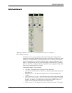
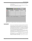
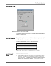
closed) will happen when the contact is open. The LED status will also update to
reflect polarity status.
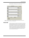
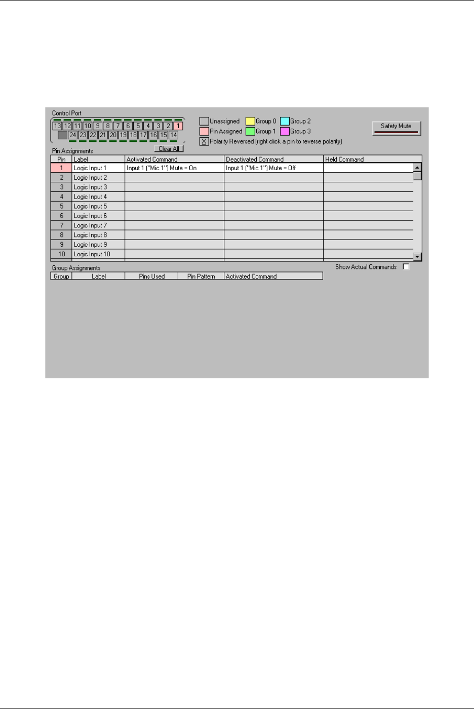
Figure 16 shows an assignment of Pin 1 to mute Input 1 when active (i.e., the contact
closed) and to unmute when inactive (contact open)..
L
OGIC
O
UTPUT
The L
OGIC
O
UTPUT
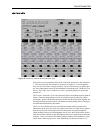
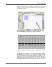
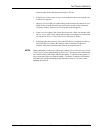
page allows the user to assign a status function to one of the 20
logic status outputs. The status functions could include AEC On or Off, AGC On or
Off, NOM Attenuation, Camera Gating, Gating, Mic or Line Level, Muting, Noise
Cancellation, and Phantom Power On or Off. To assign a status function to the status
pin, click on the pin. This will enable the A
CTIVATED
and D
EACTIVATED
control win-
dows. Right click in the A
CTIVATED
or D
EACTIVATED
field to pick a status off the
menu list, or type the command in directly. As with the Logic Input pins, the S
HOW
A
CTUAL
C
OMMAND
button will show the command syntax.
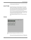
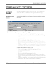
To create status output that is a logical combination of particular inputs or outputs, use
the logical syntax (+, 0, or 1). For instance, to create a status output that will be set
when Input Channels 1 AND 3 are muted, the syntax is ’MUTE*1.1.....’. To
create a muting status output that will be set when Input Channels 1 OR 3 are muted,
the syntax is ’MUTE*+.+.....’. Notice that the MUTE* status command can take
up to 12 arguments, one for each input. The gating status command GATE* takes 8
arguments since only Inputs 1-8 can be gated.
The polarity of the outputs can also be changed by right-clicking on the pin number.
Figure 16. Logic pin 1 is assigned to mute input 1 when activated and unmute when deactivated.