DEVICE PARAMETERS
Conference Composer User Guide 8 Technical Support: 800.932.2774
DEVICE PARAMETERS
Each device in Conference Composer is represented by a list of sub-entries for that
device. For the Vortex, those fields are S
YSTEM
, M
IC
/L
INE
I
NPUTS
, etc. as shown in
Figure 4. By clicking on the Device (EF2280:00 in Figure 4) you bring up the S
YS
-
TEM
page as shown in Figure 6. Notice that each S
YSTEM
page has tabs correspond-
ing to the list of sub-entries in Figure 4. Clicking on either a tab or the field name will
bring you to a page with specific controls for that set of functions.
S
YSTEM
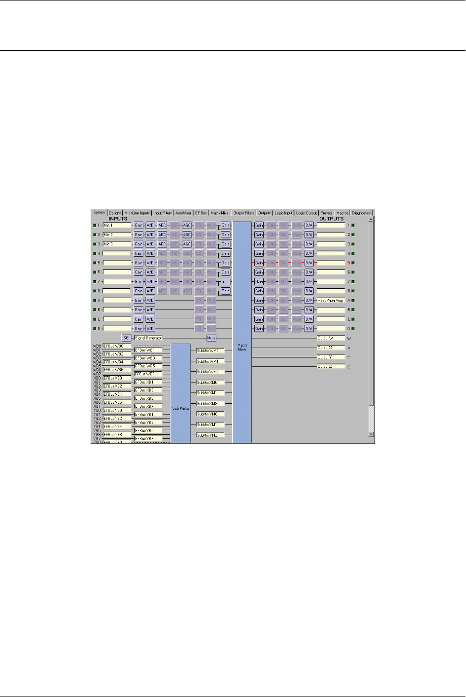
The S
YSTEM
Page presents you with a block diagram of the Vortex. It allows you to
quickly enter text labels for inputs and outputs (this can also be done on all the other
pages too), and see the signal flow from inputs to outputs. Holding the cursor over a
particular block in the block diagram will show signal flow information from inputs
to outputs or outputs to inputs depending on where you hold the mouse. By holding
the cursor over any output block, you can see the all the inputs that map to the partic-
ular output. You may enable/disable specific features by left clicking on the blocks in
the S
YSTEM
Page. If a block is grayed out, it is turned off.
When connected to a device, the Signal Activity LEDs mapped to the inputs and out-
puts of the S
YSTEM
Page (See Figure 7) show the signal activity. This indicator is
independent of the gating indicators -- it simply indicates when the input or output has
signal level above the Activity Threshold. The Activity Threshold for what consti-
tutes activity is set on the O
PTIONS
Page -- it is in the M
ISCELLANEOUS
section. If you
set this level too high, the threshold may be too high and the signal activity LED will
Figure 6. Vortex System tab shows the block diagram of the device.


