


DEVICE PARAMETERS
Conference Composer User Guide 16 Technical Support: 800.932.2774
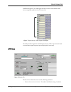
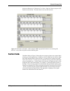
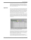
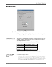
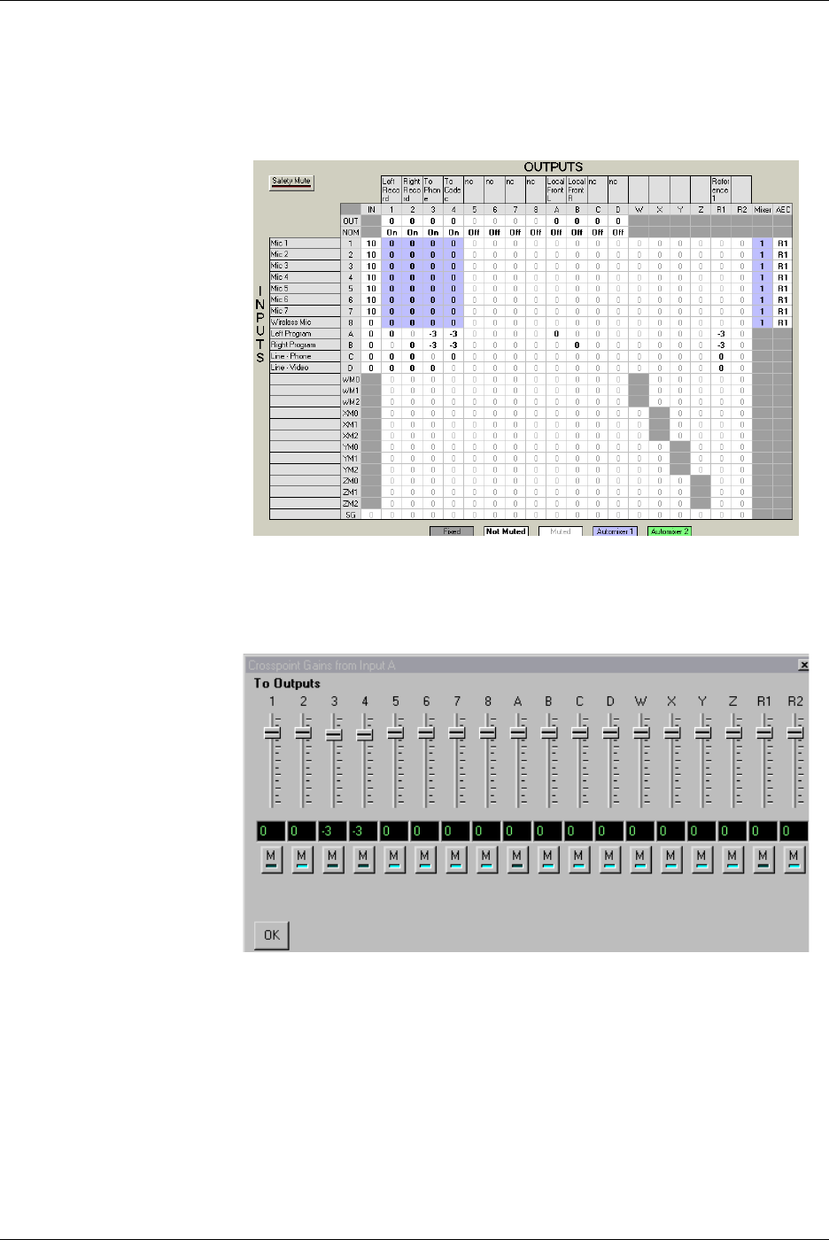
To change the gain of an entire row or column you may simply click on the column or
row header (any of the labels 1-D on the columns or the rows) to see a collection of
sliders as shown in Figure 13.
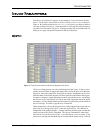
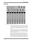
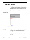
The outputs R1 and R2 correspond to the echo canceller references R
EF
1 and R
EF
2.
While these outputs are not physical outputs on the product, they allow you to build
the echo canceller reference without using physical outputs from the device. In the
example in Figure 12, we used stereo program audio and consequently had a local left
output (Output C) and a local right output (Output D) in the room. The echo canceller
reference R1 included both the codec audio (Input A), the phone add audio (Input B)
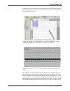
Figure 12. The full cross point matrix for a system using a phone add, a codec,
and stereo program audio. Only the bold crosspoints are unmuted.
Figure 13. Cross point slider view of how Input A is used in all the output chan-
nels.