


DEVICE PARAMETERS
© Polycom, Inc. 11 Conference Composer User Guide
M
IC
/L
INE
I
NPUTS
The M
IC
/L
INE
I
NPUTS
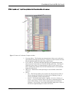
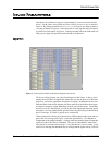
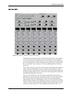
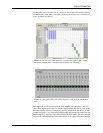
page contains all the controls required to configure the 12
inputs (8 mic/line inputs and the 4 line level inputs). Figure 9 shows a Mic/Line Input
channel, a Line Input channel, and the Signal Generator – note that you can enable/
disable an input from view with the numbered buttons on the top of the page. Once
Input 1 is configured, the user may copy those settings to the other mics by clicking
the C
OPY
S
ETTINGS
1–8 button. The same capability exists to copy the settings from
Input A to the remaining line level inputs.
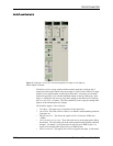
The fields for Inputs 1-8 are as follows:
•T
EXT
B
OX
. This stores up to 16 character for the input label.
•G
ATE
LED. This LED is active if the L
EVELS
button is enabled and the particular
input gates on.
•M
ETER
PER
INPUT
. This shows the signal level if it is between -20dBu and
+20dBu.
•G
AIN
SLIDER
AND
TEXT
BOX
. These allow the user to set the input gain in dB on
the channel. The value adds gain in the analog domain using digitally controlled
trimpots. For Inputs 1-8, the gain slider can provide up to 30dB of gain. For
Inputs A-D, the gain slider can provide up to 20dB of gain.
•M
IC
/L
INE
SWITCH
. This applies mic or line level gain to the Input. In Mic mode,
Figure 9. Vortex MIC
/L
INE
I
NPUTS
tab showing Mic/Line Input 1, Line Input A,
and the Signal Generator.