


DEVICE PARAMETERS
Conference Composer User Guide 14 Technical Support: 800.932.2774
M
AX
NOM set to 8. To link Vortexes together, use the B
US
M
IXER
number. Put all
the Vortexes you would like to operate as one large mixer together on the same B
US
M
IXER
number with the exception of B
US
M
IXER
0. If the B
US
M
IXER
is set to 0, the
Automixer will work independently from other connected Vortexes.
Each of the eight signal channels going into the automixer can be configured to be
part of a particular automixer (Mixer 1 or Mixer 2). If set to N
ONE
, it is not part of an
automixer and does not affect gating decisions. The gating for each channel can be
set to to F
ORCE
O
N
, F
ORCE
O
FF
, or A
UTO
.
The T
HRESHOLD
T
YPE
can either be A
DAPTIVE
or M
ANUAL
. The default is A
DAPTIVE
T
HRESHOLD
. The A
DPATIVE
T
HRESHOLD
can be set when the T
HRESHOLD
T
YPE
is set
to Adaptive. This represents how much louder the signal needs to be over the noise
floor before the microphone should be gated on. M
ANUAL
T
HRESHOLD
allows you to
set an absolute threshold that the signal needs to be greater than in order to gate on.
G
ATE
P
RIORITY
can be configured for each microphone. Priority 1 is the highest pri-
ority and Priority 4 is the lowest priority. A higher priority input takes precedence
over a lower priority input if the maximum number of open microphones (Max NOM)
is set to be less than the number of microphones assigned to that automixer.
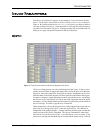
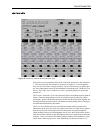
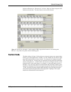
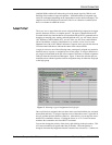
EF B
US
The EF B
US
page allows the user to configure how to combine the bus signals from
the other linked Vortexes and control which echo canceller reference is sent to other
devices as the Bus Reference. Since there can be up to 8 Vortexes linked together and
each device can put 4 different signals on the bus (W, X, Y, and Z), there are 4 subma-
trices to allow flexibility in how the signals from other devices get mixed together and
get presented to the main matrix. Figure 11 shows the EF B
US
submatrix and the fact
that there are 4 submatrices and the inputs are WB0, … WB7 for the W bus, XB0, …,
XB7 from the X bus, and the same for the Y and Z busses. The cross points can be
changed by left clicking on the cell and adjusting the gain. Cross points can be muted
by right-clicking on the cell (an unmuted crosspoint is indicated by a bolded black
value; muted is indicated by a gray value). Any of the rows of the matrices can be
configured as a mix-minus which allows the user to work with a simple mix-minus
sum of all the other devices. If more complicated mixing from other devices is
required, any of the matrix rows can have arbitrary cross points gains.
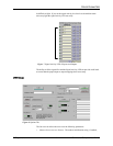
EXPORTING THE ECHO
CANCELLER
REFERENCE ON THE
EF BUS
You can set which echo canceller reference is assigned as the Bus Reference to be
used by all other linked Vortexes in the E
XPORTED
S
IGNALS
section on the page. The