


DEVICE PARAMETERS
Conference Composer User Guide 12 Technical Support: 800.932.2774
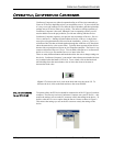
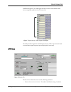
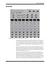
33dB of gain is added to the signal.
•P
HANTOM
P
OWER
. 24 V phantom power can be enabled or disabled (it is enabled
in Figure 9).
•M
UTE
. This button is used to mute or unmute the input signal (M
UTE
is disabled
in Figure 9).
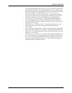
• AGC E
NABLE
. This will enable/disable the automatic gain control (AGC).
• AGC M
AX
G
AIN
. This can be used to limit the total amount of gain the AGC can
apply to the signal.
• AGC M
IN
G
AIN
. This can be used to limit the total amount of attenuation the
AGC can apply to the signal. For example, setting the AGC M
IN
G
AIN
to -10 dB
will keep the AGC from attenuating the signal too much if someone taps on the
microphone.
• AGC R
ATE
. This limits the rate of change of the AGC from between 1 to 5 dB/
sec.
•AEC E
NABLE
. This will enable or disable the acoustic echo canceller (AEC)
(AEC is enabled in Figure 9). If enabled the user can select the reference signal
to use either R
EF
1, R
EF
2, or the B
US
R
EFERENCE
.
•S
UPPRESION
. The user can also control the amount of suppression that is applied
by the echo canceller during a double-talk situation. Suppression ranges from
N
ONE
(no suppression) to Y
IKES
! mode (half-duplex).
•NC E
NABLE
. This will enable/disable noise cancellation (NC). If enabled, the
user can select the amount of noise cancellation using NC L
EVEL
. NC L
EVEL
ranges from 0 to 15 dB of cancellation.
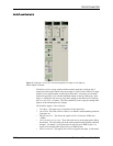
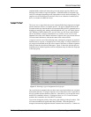
The controls for the line level Inputs A-D are simpler than the mic/line inputs. The
user can select a Gain (0dB is the default) and enable/disable Mute.
The S
IGNAL
G
ENERATOR
input allows the user to create a noise source (either pink or
white noise) for use with noise masking applications or calibration of the Vortex.
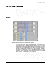
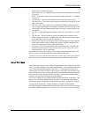
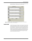
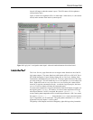
I
NPUT
F
ILTERS
Each of the inputs can have up to 5 filters of equalization. These filters include Para-
metric, Low Pass, High Pass, Low Shelf, and High Shelf. To use the filters, select the
type of filter and adjust the controls for the filter. You can adjust the controls in a
variety of ways: by typing in values in the text boxes, using the cursor up/down, using
Page Up/Page Down, or by clicking and holding the knob and moving the mouse up
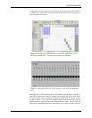
to increase the value or down to decrease the value. The frequency response of the
plots may be viewed by clicking on the G
RAPH
button.
The E
NABLE
button per filter enables/disables that particular filter on the Input. The
E
NABLE
F
ILTERS
button enables/disables all filters on the particular Input Channel.
This button toggles with the Filter Bypass buttons per Input. All filters for a particu-
lar input can be bypassed by clicking on the B
YPASS
button for that channel.
Once the settings are configured for Input Channel 1, the user may copy those settings
to all other channels using the C
OPY
C
HANNEL
1 F
ILTERS
TO
ALL
C
HANNELS
button.