


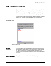
DEVICE PARAMETERS
Conference Composer User Guide 18 Technical Support: 800.932.2774
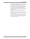
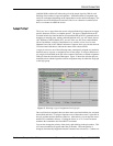
(labelled NOM) enabled will reduce the gain of the output signal by 3dB for each
doubling of the number of open microphones. NOM attenuation is computed sepa-
rately for each output, depending on the inputs that are used to build each output. The
output levels will be displayed in real-time if the L
EVELS
function is enabled (click
the L
EVELS
button to enable the levels).
L
OGIC
I
NPUT
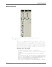
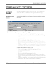
The L
OGIC
I
NPUTS
page allows the user to assign individual logic input pins to trigger
specific functions, macros, or complete presets. The types of functions that can be
executed include any function that can be controlled with an RS232 command such as
changing or ramping gains, muting, enable/disable the AEC, set AEC Mode, choose
AEC Reference, enable/disable AGC, set AGC Max, set AGC Rate, enable/disable
Noise Cancellation, set Noise Cancellation Level, set Mic or Line Level, or turn
Phantom Power On or Off. Within Conference Composer, the Logic pins also have an
LED associated with them to indicate the status of the contact closure.
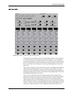
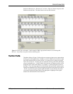
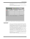
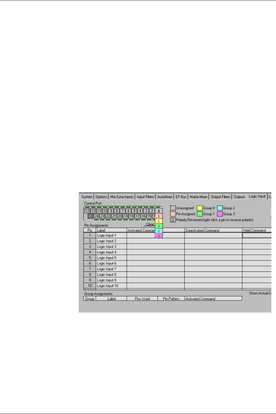
A logic pin can have one of the following states: unassigned, assigned to a particular
function, macro, or preset, or assigned to one of four groups. To assign a function to a
pin, single click and hold on the pin of the connector and select a colored assignment
of the pin from the colored boxes that appear. Figure 15 shows the selection process –
match the colors with the legend to create an assignment entry for either the single pin
or the logic group.
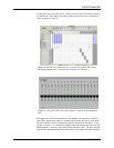
Once a pin has been assigned, there are three states associated with the pin: activated,
deactivated, and held. To assign a function to one of these three states, right click in
the cell, and then pick the function off the list. Alternatively you can type the associ-
ated RS232 command in directly. Clicking the S
HOW
A
CTUAL
C
OMMAND
button
translates the command to the actual RS232 command.
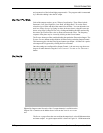
You can also change the polarity of the pin by right clicking on the pin number. This
will cause an underline to appear under the pin number. When the polarity is
changed, what normally happened when the command was activated (i.e., contact was
Figure 15. Selecting a type of assignment for a logic pin