


Register-Level Programming Appendix C
PC-OPDIO-16 User Manual C-4 © National Instruments Corporation
Programming
The pseudocode for controlling the output port of the PC-OPDIO-16 is:
1. Write to 82 hex to the Digital Control Register to configure port A as the output port and
port B as the input port.
2. Write digital value to the Port A Register to control the optically isolated digital lines
VOUT0 through VOUT7.
Note: Writing a digital 1 to the port line will give a high on the corresponding VOUT line.
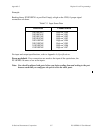
Example:
Writing binary XXXXXXX1 to port A will output a high on the VOUT0, if proper signal
connections are done. Similarly, writing a binary XXXXXX1X to port A will output a high on
the VOUT1.
Power-up default: if no connections are made to an output port, the outputs are in high
impedance state. If VCCO0 and COM0 are connected to an isolated power supply, then the
VOUT0 will be high.
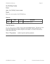
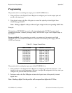
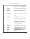
Table C-1. Output Control Data
Value Written Channel Controlled
XXXXXXX1 High on VOUT0
XXXXXX1X High on VOUT1
XXXXX1XX High on VOUT2
XXXX1XXX High on VOUT3
XXX1XXXX High on VOUT4
XX1XXXXX High on VOUT5
X1XXXXXX High on VOUT6
1XXXXXXX High on VOUT7
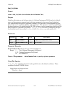
The pseudocode for reading the input port of the PC-OPDIO-16 is:
1. Write to 82 hex to the Digital Control Register to configure port B as the input port. You
should do this once in the beginning of the port A and port B configuration or every time you
configure one port the others will be reset too.
2. Perform a read on the Port B Register to detect the logical state of the optically isolated
digital lines.
Note: Reading a digital 1 at the port line will correspond to a high at the VIN line.