


Specifications Appendix A
PC-OPDIO-16 User Manual A-2 © National Instruments Corporation
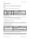
Digital logic levels .......................................................
Level Min Max
Ouput low voltage
(I
OL
= 4.0 mA)
— ±1 VDC
Ouput high voltage
(I
OH
= 250 µA)
22 VDC at
VCCO = 24 V
3 VDC at
VCCO = 5 V
—
Output low current — 7.0 mA
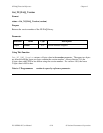
Supply current for isolated outputs
5 V outputs............................................................1 mA/channel min
24 V outputs..........................................................5 mA/channel min
Data transfer rate
2
........................................................5 kHz
Isolation........................................................................24 VDC from computer ground
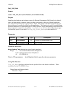
Toshiba TLP-121 Phototransistors
Current transfer ratio (CTR).........................................100% min
Type .............................................................................Rank GB
Operating conditions
Supply Voltage (Vcc) ........................................... 5 V typ, 48 V max
Forward current (If)...............................................16 mA typ, 20 mA max
Collector current (Ic).............................................1 mA typ, 10 mA max
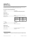
Power Requirement
Maximum power
3
........................................................500 mA at 5 VDC (±5%)
Physical
Board dimensions.........................................................10.79 by 12.06 cm (4.25 by 4.75 in)
I/O connector................................................................50-pin keyed male ribbon cable connector
Operating Environment
Component temperature............................................... 0° to 50° C
Relative humidity......................................................... 5% to 90% noncondensing
Storage Environment
Temperature .................................................................-55° to 125° C
Relative humidity......................................................... 5% to 90% noncondensing
2
The output data transfer rates are limited by the load resistor and the switching characteristics (turn-on time,
switching time, and turn-off time) of the optical isolator used on the board. The transfer rates also depend on the
computer, CPU speed, and software used.
3
This does not include the power consumed by external devices connected to the fused +5 VDC supply.