


Signal Connections Chapter 3
PC-OPDIO-16 User Manual 3-6 © National Instruments Corporation
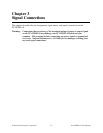
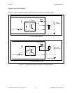
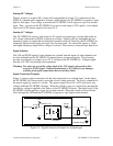
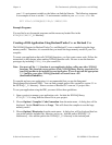
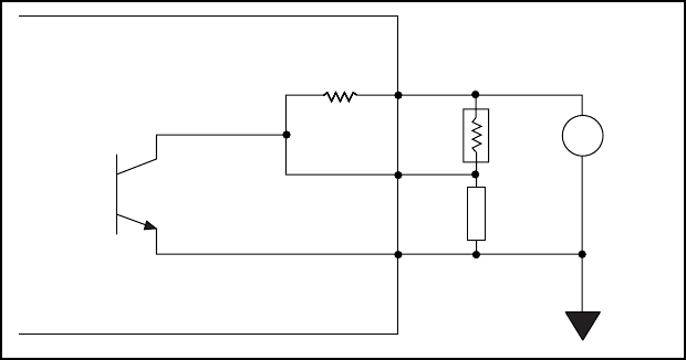
Increasing Switching Frequency for TTL Loads
You can increase the switching frequency for the TTL loads by putting a resistor in parallel to
VCCO and VOUT. This parallel arrangement will reduce load resistance and increase switching
frequency. You can choose a value of Ro, as shown in Figure 3-3, in such a way that the
effective resistance from the parallel combination of 5.6 kΩ and Ro is about 1 kΩ. This
resistance will increase the switching frequency at the output to about 8 kHz, depending on your
software and the computer used.
5.6 kΩ5.6 kΩ5.6 kΩ
PC-OPDIO-16
TLP121
5.6 kΩ
+
-
Load
VCC0
VOUT
COM
Supply
Isolated Ground
5 V
Ro
Figure 3-3. Resistor in Parallel to Increase the Switching Frequency
Power-on Condition
At power up, VOUT will be high if the supply is connected to the VCCO terminal.
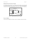
Optically Isolated Digital Input
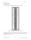
I/O connector pins 25 through 40 shown in Figure 3-1 represent the optically isolated input
signal pins.
Input Channels
The optically isolated inputs of the PC-OPDIO-16 consist of a bidirectional light-emitting diode
and a resistor for current limiting. The PC-OPDIO-16 has eight isolated input channels. Each
channel has its own isolated ground and input signal.
Maximum input voltage (VIN) +24 VDC or 24 VAC
Note: Maximum data rate that can be sensed at the input is limited by the hardware to 1 kHz.
But the data rate that can be sensed at input may be slower than 1 kHz depending on
your software and CPU speed.