© National Instruments Corporation 5-1 PC-OPDIO-16 User Manual
Chapter 5
Theory of Operation
This chapter describes the theory of operation for optically isolated digital I/O on the
PC-OPDIO-16. This chapter also discusses using NI-DAQ functions with the PC-OPDIO-16
board.
Functional Overview
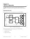
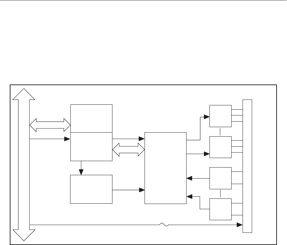
The block diagram in Figure 5-1 shows a functional overview of the PC-OPDIO-16.
PC I/O Channel
Data/
Address
Control
Plug and Play
Interface
PC I/O
Channel
Interface
Address
Select and
Control
Control
82C55A
Digital
I/O
Control
+5 V
1A Fuse
A<0..1>
PA7
PA0
PB0
PB7
TLP121
TLP121
LDA210
LDA210
Back Panel Connector
•
•
•
•
•
•
•
•
•
•
•
•
VCCO0
VOUT0
COM0
VIN7
IGND7
+5 V
DGND
Data
D<0..7>
Figure 5-1. PC-OPDIO-16 Block Diagram
The following are the major components making up your PC-OPDIO-16 board:
• I/O channel interface circuitry
• Digital I/O circuitry
• Optical isolation circuitry


