


Chapter 3 Signal Connections
© National Instruments Corporation 3-3 PC-OPDIO-16 User Manual
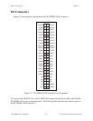
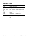
Signal Connection Descriptions
Pin Signal Name Description
1, 4, 7, 10,
13, 16, 19,
22
VCCO<0..7>
Isolated Vcc for Output, channels 0 through 7—This signal is the Vcc for the
output channels. Range: +5 V to +24 V.
2, 5, 8, 11,
14, 17, 20,
23
VOUT<0..7> Isolated Output, channels 0 through 7—This signal is the optically isolated
digital output line. VOUT7 is the MSB; VOUT0 is the LSB.
3, 6, 9, 12,
15, 18, 21,
24
COM<0..7> Common, channels 0 through 7—This signal is the reference level from which
VOUTx is measured. It may be the isolated GND at the user end.
25. 27, 29,
31, 33, 35,
37, 39
IGND<0..7> Isolated Input Ground, channels 0 through 7—This signal is the optically
isolated ground for the input channels. The input signal will be referenced to
this ground.
26, 28, 30,
32, 34, 36,
38, 40
VIN<0..7> Isolated Input Voltage, channels 0 through 7—This signal is the optically
isolated digital input line. VIN7 is the MSB; VIN0 is the LSB.
41–47 NC These pins are not connected.
48, 50 DGND Digital Ground—These pins are connected to the internal ground signal of the
PC-OPDIO-16 board. This is not an isolated ground.
49 +5 V +5 V—This output signal carries 1 A maximum output. It is referenced to
DGND.