


Chapter 5 Theory of Operation
© National Instruments Corporation 5-3 PC-OPDIO-16 User Manual
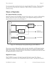
designed around an 82C55A programmable peripheral interface (PPI). Two of the 82C55A ports
are used in the PC-OPDIO-16; port A is used for output, and port B is used for input.
Optical Isolation Circuitry
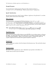
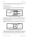
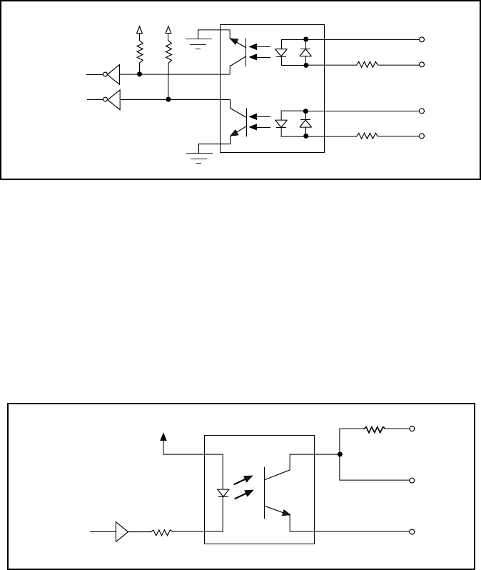
The eight bits of digital input are optically isolated by using four LDA210 solid-state photo
couplers. The optical isolation circuitry for input is shown in Figure 5-3 (only two input
channels, 0 and 1, are shown).
LDA210
3.3 kΩ
Port B
Digital Logic
+5 V
VIN0
+5 V
3.3 kΩ
VIN1
IGND0
IGND1
Figure 5-3. Optical Isolation Circuitry for Input
Each LDA210 provides optical isolation for two channels of input. The digital input signals
from VIN are buffered to improve and invert the logic levels before being passed to the 82C55A
PPI. The IGND pin of each channel connects to the isolated ground reference for the digital
signal of the corresponding channel.
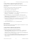
Optical isolation of the eight bits of digital output is provided by eight Toshiba TLP121 photo
couplers. The optical isolation circuitry for output is shown in Figure 5-4 (only channel 0 is
shown).
5.6 kΩ5.6 kΩ5.6 kΩ
TLP121
470 Ω
5.6 kΩ
Port A
Digital Logic
+5 V
VCCO0
VOUT0
COM0
Figure 5-4. Optical Isolation Circuitry for Output
One photo coupler is used for optical isolation at each channel of output. Signals from port A of
the 82C55A PPI are buffered to improve logic levels. Digital output signals are available at the
VOUT pin of each channel. VCCO is connected to the voltage reference of the digital signal of
the corresponding channel and COM is the reference level from which VOUT is measured.