


7
Section 1: Assembly & Set-up
3/18/15
SBL2566, SBL2574, & SBL2584 with S/N 891531+ Snow Blowers 370-478M
Table of Contents
Section 1: Assembly & Set-up
Skid Steer/Tractor Requirements
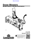
The SBL2566, SBL2574, & SBL2584 Snow Blowers are
designed to attach to skid steers. The SBL2566 can also
be attach to a tractor loader with Land Pride’s 3-point
mounted hydraulic reservoir system (HRS) or equivalent
system mounted on the back. The skid steer and/or
tractor/HRS must meet the following minimum
requirements:
SAE Lift Capacity . . . . . . . . . . . . . . . . . . . . . 1200 lbs
Hitch Type . . . . . . . . . . . . . . . Skid steer/loader plate
Hydraulic Pressure Rating . . . . . . . . .2500 - 3500 psi
Low Volume Motors & Hoses . . . . . . . . . .12 - 19 gpm
Medium Volume Motor & Hoses . . . . . . . 20 - 26 gpm
High Volume Motor & Hoses . . . . . . . . . 27 - 33 gpm
Hydraulic Hoses. . . . . . . . . . . . . 2 - Hydraulic outlets
Case Drain Hose . . . . . . . . . . . . . 1 - Hydraulic outlet
Skid Steer Weight . . . . . . . . . . . . . See warning below
!
WARNING
Ballast weights may be required to maintain steering control.
Refer to your skid steer or tractor Operator’s Manual to
determine proper ballast requirements.
Torque Requirements
Refer to “Torque Values Chart” on page 36 to
determine correct torque values for common bolts.
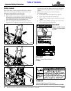
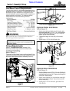
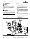
Loading & Unloading
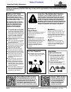
Refer to Figure 1-1:
There are two lifting holes (one on each end panel). Use
these holes to attach lift chains during loading/unloading
and while installing skid shoes in assembly & set-up.
Lift Points
Figure 1-1
IMPORTANT: The skid steer or tractor mounted
hydraulic reservoir system must be equipped with a
case drain system.
35599
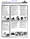
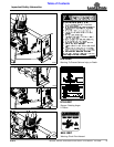
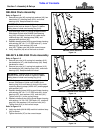
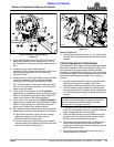
Outer Skid Shoe Assembly (Right-Hand Shown)
Figure 1-2
Optional Outer Skid Shoes
Refer to Figure 1-2:
1. Attach outer right-hand skid shoe (#1) to the right-
hand side panel with 1/2"-13 x 1 1/4" GR5 carriage
bolts (#2) and hex flange lock nuts (#3) using the
bottom square holes as shown.
2. Tighten hex flange lock nuts (#3) to the correct
torque.
3. Repeat steps 1 & 2 for the left-hand side.
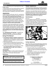
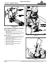
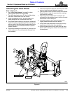
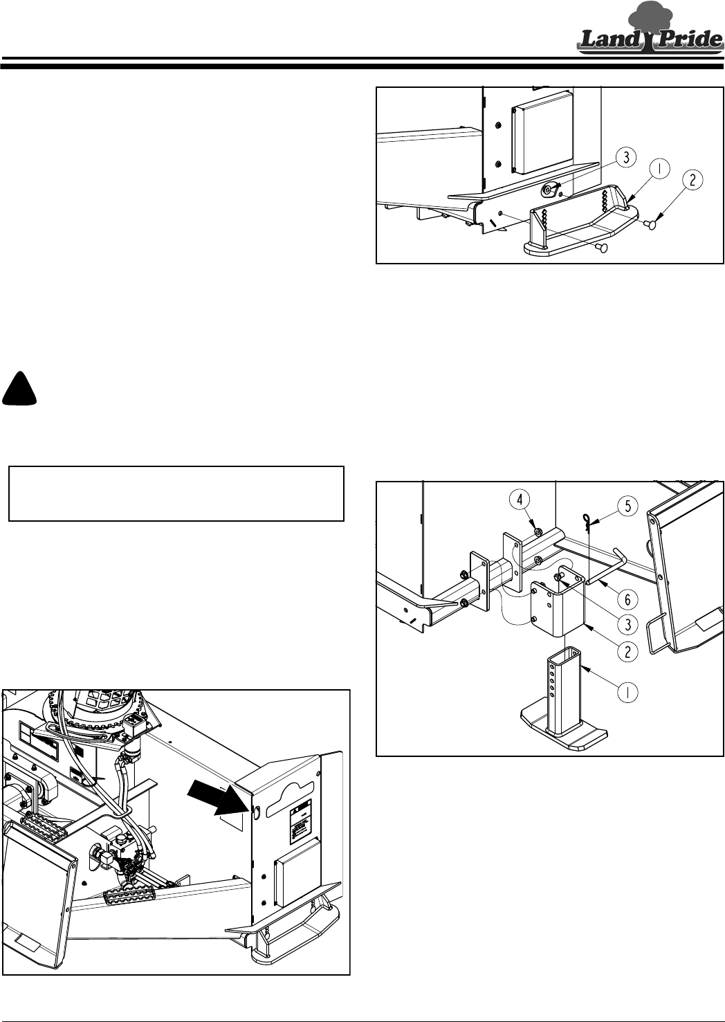
Inner Skid Shoe Assembly (Left-Hand Shown)
Figure 1-3
Optional Inner Skid Shoes
Refer to Figure 1-3:
1. Attach skid shoe mount (#2) to the back, left side of
the Snow Blower with 1/2"-13 x 1 1/2" GR5 bolts (#3)
and hex flange lock nuts (#4). Tighten hex flange lock
nuts to the correct torque.
2. Attach inner skid shoe (#1) to skid shoe mount (#2)
with bent pin (#6) as shown. Secure bent pin with
hairpin cotter (#5).
3. Repeat steps 1 & 2 for the back, right side of the
Snow Blower.
37225
37226