


18
Section 3: Options
SBL2566, SBL2574, & SBL2584 with S/N 891531+ Snow Blowers 370-478M
3/18/15
Table of Contents
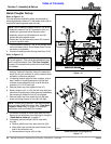
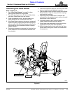
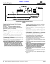
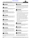
Tractor Mounted Toggle Switch Control Harness
Figure 3-4
FOUR CONNECTORS THIS END
CONNECTS TO EQUIPMENT SOLENOIDS
20 AMP FUSE
TWO EYELETS
CONNECTS TO 12V
POWER SOURCE
35809
See Figure 4-1
on page 20.
Tractor Control Harness With 2 Eyelets
Refer to Figure 3-4:
370-133A CONTROL HARNESS TRACTOR
This harness is used only with tractor mounted Snow
Blowers and consist of the following:
• Power cord (#1): Attaches to tractor battery and control
box (#2).
• Control box (#2): Mounts in a convenient location for
the operator to access from the seat. See also Figure
4-1 on page 20.
• Wire harness (#3): Attaches to control box (#2) and
terminates at the front of one of the loader arms.
• Wiring harness (#4): Attaches to wire harness (#3) and
solenoids at the Snow Blower.
• Cable ties (#5): For securing wire harnesses (#1, #3,
& #4) to the tractor loader and Snow Blower.
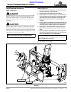
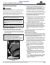
Installation Instructions for Tractor Harness
1. Before doing anything else, determine the path
power cord (#1) will travel from tractor battery to
control box (#2), location of control box (#2), and
path wire harness (#3) will travel from control box to
the front end of the loader arm. Make sure control
box is mounted in an area where the operator can
operate the toggle switches easily from the tractor
seat. Method of mounting the control box is to be
determined by the customer.
2. Disconnect negative ( - ) black power cord from its
battery post.
3. Attach positive ( + ) red wire eyelet on end of power
harness (#1) to the battery’s positive ( + ) post and
tighten fastener hardware.
4. Attach negative ( - ) black wire eyelet on end of power
harness (#1) and negative ( - ) black power cord to
the battery’s negative ( - ) post and tighten.
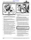
5. Route power cord (#1) from the battery to the
predetermined location of control box (#2).
6. Mount toggle switch control box (#2) to the tractor
using hardware furnished by customer.
7. Plug power cord (#1) and wire harness (#3) to control
box (#2).
8. Route wire harness (#3) to the front end of one of the
loader arms.
9. Make any final adjustments to wire harness (#3) and
power cord (#1) and make sure wire harness (#4)
can reach from solenoids at the Snow Blower to
connector at the end of wire harness (#3).
10. Secure power cord (#1) and wire harness (#3) with
cable ties (#5).
11. Connect 6 pin connector on end of wire harness (#4)
to wire harness (#3).
12. Continue with step 4 under “Solenoid Hook-up” on
page 12.