


12
Section 2: Equipment Hook-up & Unhook
SBL2566, SBL2574, & SBL2584 with S/N 891531+ Snow Blowers 370-478M
3/18/15
Table of Contents
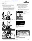
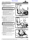
Hydraulic Hose Hook-up
!
DANGER
Hydraulic fluid under high pressure can penetrate skin. Wear
protective gloves and safety glasses or goggles when working
with hydraulic systems. Use a piece of cardboard or wood
rather than hands when searching for hydraulic leaks. If
hydraulic fluid is injected into the skin or eyes, it must be
treated by a doctor familiar with this type of injury within a few
hours or gangrene may result. DO NOT DELAY.
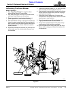
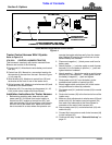
Refer to Figure 2-4 on page 13:
Two high pressure hydraulic outlets are required for the
hydraulic motor and one outlet for the case drain.
1. Route hydraulic hoses along the most convenient path
to access your skid steer or tractor mounted hydraulic
reservoir couplings.
o
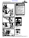
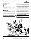
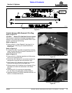
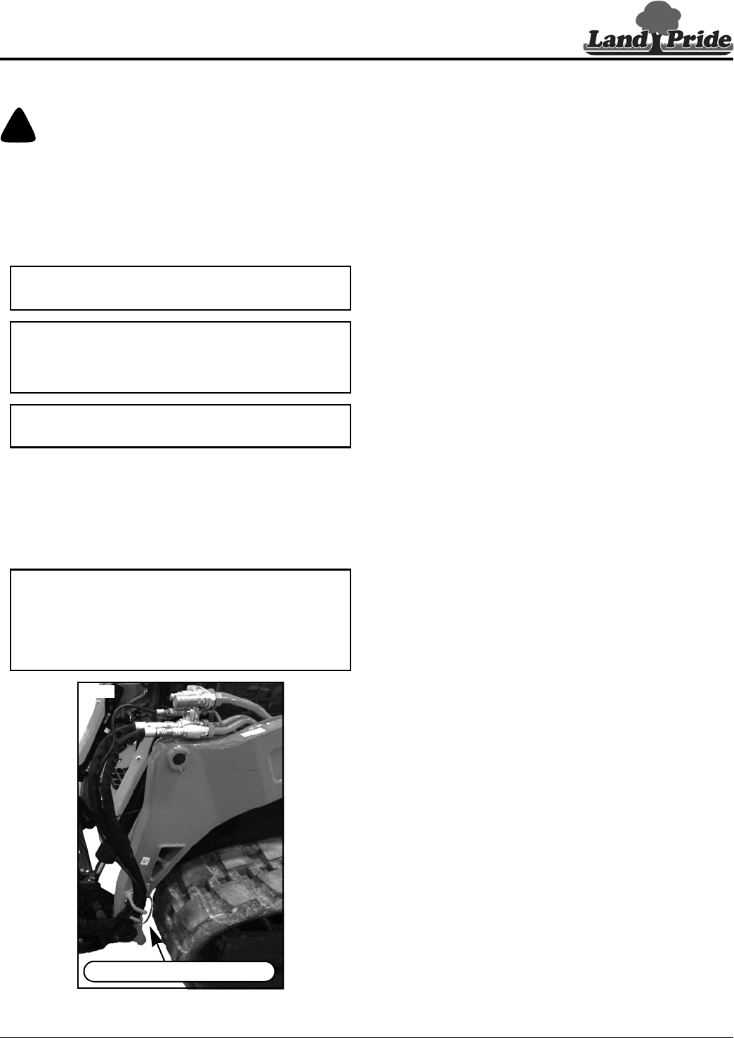
Kubota SVL Hose Stay
Figure 2-2
IMPORTANT: Collect and dispose all oil spills and
leaks in an environmentally safe manner.
IMPORTANT: Hose routing is the responsibility of
the owner/operator of the Snow Blower. Pinched
and/or stretched hoses are not covered under the
warranty.
IMPORTANT: Make sure all coupler fittings are
clean before connecting them to skid steer couplers.
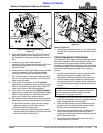
NOTE: If attaching to a Kubota SVL skid steer, route
hydraulic hoses through Kubota’s SVL Hose Stay
Kit #S6689 as shown in Figure 2-2 below.
Purchase SVL Hose Stay Kit #S6689 through your
nearest Kubota dealer. Refer to the SVL skid steer
Operator’s Manual for additional instructions.
37394
SVL Hose Stay Kit #S6689
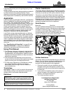
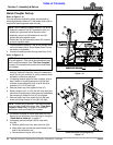
2. Clean quick connect couplers of dirt and then
connect couplers (#1 & #2) to the skid steer couplers
or couplers at the tractor mounted hydraulic
reservoir. Make sure quick connect couplers have
fully engaged. If they have not, check the following:
a. Make sure couplers are same size and type.
b. Make sure hydraulic pressure has been released.
3. If case drain line is fitted with the optional coupler,
then connect that coupler (#3) to the tank/sump
coupler and skip to step 5 below.
4. If screwing case drain line directly to the tank/sump:
a. Remove plastic cap and wrap teflon tape around
pipe threads on end of case drain line (#3).
b. Screw case drain line (#3) to your equipment’s
tank/sump port until tight. All required adapter
fittings are supplied by customer.
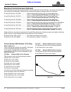
5. Turn auxiliary hydraulics on to check impeller
rotation. The impeller should rotate counterclockwise
viewed from the operator’s seat and clockwise
viewed facing impeller and auger from the front. If
impeller rotates incorrectly, switch male and female
couplers on the hydraulic hoses and reconnect
hoses.
6. Cable ties to be added at end of solenoid hook-up.
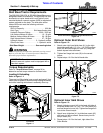
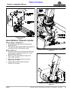
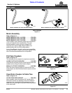
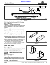
Solenoid Hook-up
Refer to Figure 2-3 on page 13:
There are six optional wiring harnesses and all connect
the same way to the Snow Blower solenoids (#1 & #2) but
connect differently to the skid steer or tractor. See pages
16 thru 18 for a detailed descriptions of all six.
1. Skip to step 3 if optional wire harness (#4) has a 6 pin
connector. Otherwise, continue with step 2 below.
2. If solenoid harness has a 14 pin connector, attach
harness to the 14 pin connector located on the end of
the loader arm. Skip to step 4 on this page.
3. There are three toggle switch control harnesses
available. Two are for skid steer mounted Snow
Blowers and one is for tractor mounted Snow
Blowers.
• Install “Control Harness With Deutsch 2 Pin
Plug” using instructions in manual 370-452M
included with this kit. See page 17 for harness
description.
• Install “Skid Steer Control Harness With 2
Eyelets” using instructions in manual 370-349M
included with this kit. See page 19 for harness
description.
• Install “Tractor Control Harness With 2 Eyelets”
using “Installation Instructions for Tractor
Harness” on page 18.