


8
Section 1: Assembly & Set-up
SBL2566, SBL2574, & SBL2584 with S/N 891531+ Snow Blowers 370-478M
3/18/15
Table of Contents
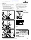
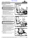
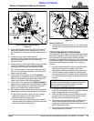
SBL2566 Chute Assembly
Refer to Figure 1-5:
1. Remove hex nuts (#8), spring lock washers (#9), hex
head bolts (#7), bearing strap (#2A), and chute
bearings (#4). Keep hardware for reuse.
2. With discharge chute (#1) facing straight forward.
Slide base of chute over UHMW chute bearing
ring (#10) until base of chute is fully under chute
rotational stop (#5), bearing strap (#2B), and
engaged with sprocket (#3).
3. Reattach bearing strap (#2A) to snow blower housing
with existing 3/8"-16 x 1 1/2" GR5 bolts (#7), chute
bearings (#4), lock washers (#9), and
nuts (#8). Tighten nuts (#8) to the correct torque.
4. Verify stop bolts (#6) are at the back as shown.
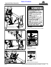
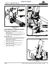
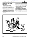
SBL2574 & SBL2584 Chute Assembly
Refer to Figure 1-5:
1. Remove hex nuts (#10), spring lock washers (#12),
hex head bolts (#7), and rotational stop (#6). Keep
hardware for reuse.
2. Remove hex nuts (#11), spring lock washers (#13),
hex head bolts (#9), bearing strap (#2A), and chute
bearings (#5). Keep hardware for reuse.
3. With discharge chute (#1) facing straight forward as
shown. Slide base of chute over UHMW chute
bearing ring (#14) until base of chute is fully under
remaining bearing straps (#2B & #2C) and engaged
with sprocket (#4).
4. Reattach bearing strap (#2A) to snow blower housing
with existing 3/8"-16 x 1 1/2" GR5 bolts (#9), chute
bearings (#5), lock washers (#13), and nuts (#11).
Tighten nuts (#11) to the correct torque.
5. Reattach rotational stop (#6) to Snow Blower housing
with existing 1/4"-20 x 3/4" GR5 bolts (#7), rotational
stop (#6), lock washers (#12) and hex nuts (#10).
Tighten nuts (#10) to the correct torque.
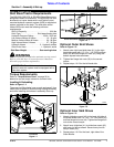
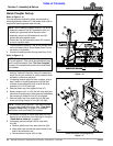
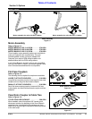
Refer to Figure 1-6:
6. Verify stop bolts (#8A & #8B) are left of rotational stop
(#6) as shown.
7. Tighten hex bolts (#7) to the correct torque.
IMPORTANT: Position chute (#1) facing straight
forward to the front as shown in Figure 1-4 before
sliding base of chute over bearing ring (#10).
IMPORTANT: Position chute (#1) facing straight
forward to the front as shown in Figure 1-5 before
sliding base of chute over bearing ring (#14).
SBL2566 Chute Assembly
Figure 1-4
SBL2574 & SBL2584 Chute Assembly
Figure 1-5
SBL2574 & SBL2584 Rotational Stop Bar Set-up
Figure 1-6
37432
35600
35601