


10
Section 1: Assembly & Set-up
SBL2566, SBL2574, & SBL2584 with S/N 891531+ Snow Blowers 370-478M
3/18/15
Table of Contents
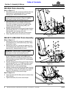
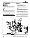
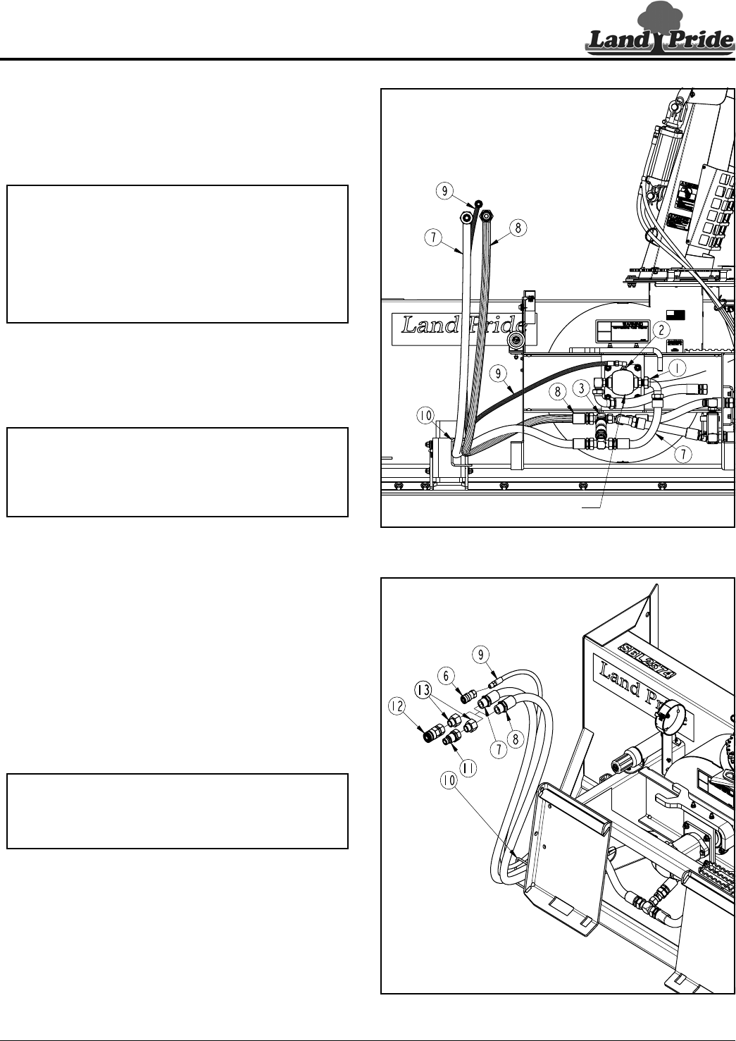
Quick Coupler Set-up
Refer to Figure 1-10
Two high pressure hydraulic outlets are required for
attaching hydraulic hoses (#7 & #8) and a third outlet is
required for attaching case drain line (#9).
1. Thread hydraulic hoses (#7, #8, & #9) through holes
on the left-hand side of Snow Blower frame. Holes
not shown in illustration.
2. Continue threading hoses through hose loop (#10).
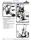
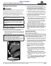
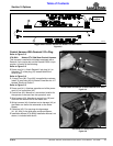
Refer to Figure 1-11
3. Consult your skid steer Operator’s Manual or
Auxiliary Hydraulic Reservoir Manual to determine
which line on your machine is under pressure when
locked for continuous operation.
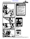
4. If installing optional large flat face couplers, skip to
step 5 below. If installing optional small flat face
couplers, screw adapters (#13) to small flat face
couplers (#11 & #12) until tight.
5. Remove plastic cap from hydraulic line (#7).
6. Select couplers (#11 or #12) that will mate with your
machine’s coupling that is under pressure and attach
that coupling to hydraulic line (#7) and tighten.
7. Remove plastic cap from hydraulic line (#8) and
screw remaining coupler to line (#8) until tight.
8. If customer chooses to screw case drain line (#9)
directly to the tank/sump, then skip step 9 and go to
“Snow Blower Hook-up” on page 11.
9. If attaching optional coupler (#6) to case drain
line (#9):
a. Remove plastic cap from case drain line (#9).
b. Wrap teflon tape around the pipe threads on the
end of the case drain line.
c. Screw optional coupler (#6) on tight.
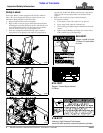
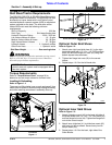
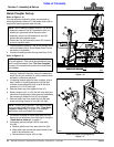
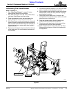
NOTE: How to identify hydraulic lines (#7, #8, & #9):
• Hydraulic pressure line (#7) attaches to port (#1)
located on right-hand side of impeller motor.
• Hydraulic return line (#8) attaches to tee (#3)
located beneath impeller motor.
• Case drain line (#9) attaches to port (#2) located
on top of impeller motor.
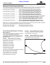
NOTE: Flat face couplers (#11 & #12) and adapters
(#13) are optional. They can be purchased from your
local Land Pride dealer. See “Flat Face Couplers”
on page 15 for detailed information and Land Pride’s
part number.
NOTE: Coupler (#6) is optional. It can be purchased
from your local Land Pride dealer. See “Case Drain
Coupler & Cable Ties” on page 15 for detailed
information and Land Pride’s part number.
Hydraulic Hose Layout (View Without Hitch Plate)
Figure 1-10
Quick Disconnect Coupling Set-up
Figure 1-11
IMPELLER MOTOR
35605
35604