MAINTENANCE
OM 0400-A
24
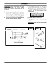
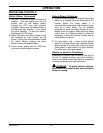
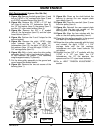
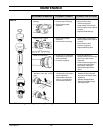
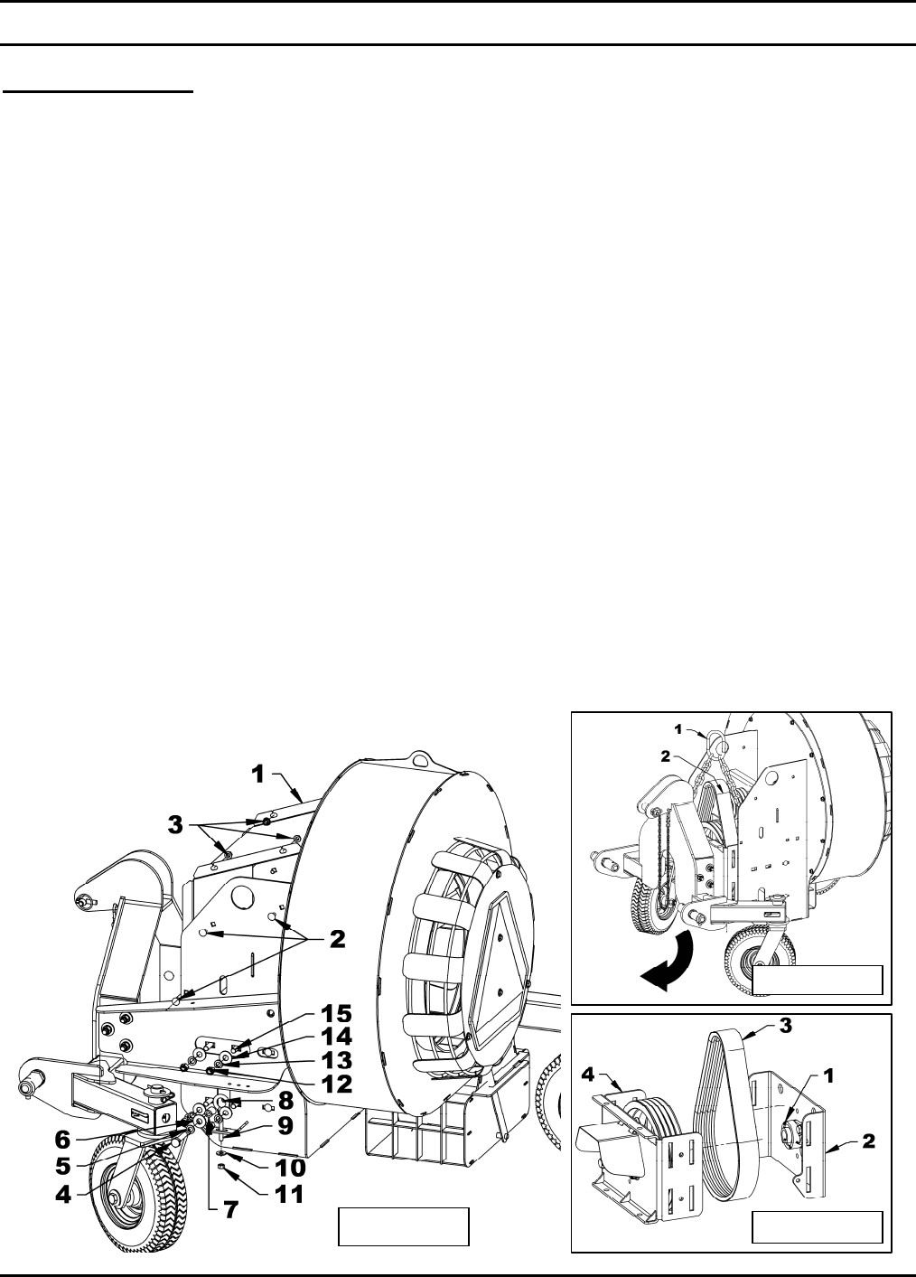
Figure 10a
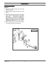
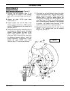
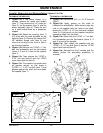
Figure 10b
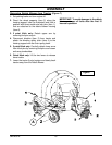
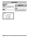
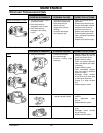
Figure 10c
Belt Replacement (figures 10a-10b-10c)
1. Figure 10a: Remove the belt guard (item 1) and
the six 3/8"NC x 3/4" carriage bolts (item 2) and
six 3/8"NC serrated flange nuts (item 3).
2. Figure 10a: Remove the 1/2"NC x 2 1/2" bolt
hex (item 4) and the 1/2" lockwasher (item 5),
the 1/2" flat washer (item 6), the spacer (item 7)
and the 1/2" nylon insert locknut (item 8).
3. Figure 10a: Remove the 3/8" x 5" eyebolt
(item 9), the flat washer (item 10) and the nylon
insert locknut (item 11).
4. Figure 10a: Perform the 2 and 3 steps for the
second eyebolt.
5. Figure 10a: Remove the eight 1/2"NC nylon
insert locknuts (item 12), the eight 1/2"
lockwashers (item 13), the eight 1/2" (9/16" int.)
flat washers (item 14) and the eight 1/2"NC x 1
3/4" carriage bolts (item 15).
6. Figure 10b: With a hoist, raise the drive pulley
assembly (item 2) with a two hook chain (item 1)
to well balance the weight. (This assembly
weights approximately 75 pounds).
7. Put the drive pulley assembly to the ground and
move forward the debris blower.
8. Figure 10c: Remove the two set screws of the
bearing (item 1).
9. Figure 10c: Clean up the shaft behind the
bearing to remove the rear support plate
more easily (item 2).
10. Figure 10c: Place the new belt (item 3) over
the drive pulley (item 4).
11. Figure 10c: Reinstall the rear support plate
(item 2) and the two set screws on the
bearing (item 1) without tightening.
12. Figure 10c: Align the four notches with the
ones on the drive pulley assembly (item 4).
13. Place the drive pulley assembly to the ground
and back up the debris blower over it.
14. Raise the drive pulley assembly with the hoist
and reinstall the eight 1/2"NC x 1 3/4"
carriage bolts with the flat washers,
lockwashers and nylon insert locknuts. Do
not tighten.
15. Reinstall the two 3/8" x 5" eyebolts with the
1/2"NC x 2 1/2" hex bolts, the 1/2"
lockwashers, the 1/2" flat washers, the
spacers and the 1/2" nylon insert locknuts.
16. Go to «BELT TENSION ADJUSTMENT »
section.


