


9
SECTION III. INSTALLATION
This section contains instructions for installing the
Front Hitch System on the tractor. If the optional
Hydraulic Angling Kit (190-288-100) is also being
installed, refer to the installation instructions in its
Operator’s Manual as you complete each of the
following steps. Some of the instructions for
installation of the Angling Kit will supersede or
supplement instructions for the Front Hitch.
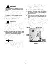
A. INSTALL THE HYDRAULIC VALVE.
WARNING
Allow the tractor to cool if recently operated.
CAUTION
Position a suitable container to catch any oil leak-
age that may occur when disconnecting the hy-
draullic lines. Obey all applicable laws for disposal
of oil.
NOTE
Early production tractors were built with a stan-
dard O-ring and a backup O-ring on the hydrau-
lic lines at their connections to the hydraulic
valve. When disconnecting the hydraulic lines,
make certain to note whether there are one or
two O-rings at each connection (O-rings may
stick in valve bores). Extra backup O-rings have
been provided with this kit for use if needed.
The backup rings can be used to ensure tight
connections at the hydraulic valves.
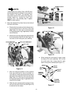
NOTE
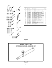
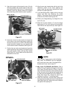
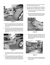
Tractors built after Mfg. Code 1D178G20023
are equipped with a flexible hose instead of the
hard hydro return tube (See Figure 13). If
equipped with the flexible hose, skip step 1 and
refer to step 2
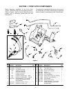
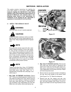
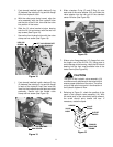
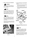
1. Mfg. Code 1D178G20022 and Before. Secure
the ‘T’ fitting to avoid damaging the hydraulic lines
and loosen the coupling nut; then remove the hex
screw and valve clamp to remove the standard
hydro return tube (See Figure 12). Remove the O-
ring and backup ring (if applicable) from the tube.
Retain the valve clamp, screw and backup ring.
Figure 12
Figure 13
2. Mfg. Code 1D178G20023 and After. Remove the
hex screw and valve clamp to disconnect the
hydro return hose from the valve (See Figure 13).
Use care to avoid losing the O-Ring and backup
ring (if applicable) from the end of the hose. Retain
the valve clamp and screw.
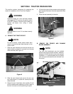
3. Remove the hex cap screw and lock nut fastening
the rear valve mtg. bracket to the tractor frame
(See Figure 12 or 13). Retain the fasteners.
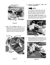
4. Remove the two hex screws and lock nuts
securing the hydraulic valve between the front and
rear valve mtg. brackets (See Figure 13 and 14).
Remove and retain the rear mtg. bracket and lock
nuts.
HYDRO
RETURN
TUBE
COUPLING NUT
VALVE CLAMP
REAR VALVE
MTG. BRACKET
HYDRAULIC
VALVE
‘T’ FITTING
HEX SCREW
HEX SCREW
AND LOCK NUT
HYDRO
RETURN
HOSE
REAR VALVE
MTG. BRACKET
HEX SCREW
AND LOCK NUT
HEX SCREW
VALVE CLAMP
HEX LOCK
NUTS