


20
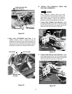
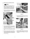
C. REINSTALL THE SEAT ASSEMBLY.
1. Lay the seat assembly on its side on top of the
fender and plug the wire harness connector onto
the seat switch. Refer to Figure 5.
2. Carefully position the seat assembly on the fender.
Align the rear slide channel holes and fender holes
with the mounting holes of the frame. Fasten with
two torx head (or socket hd.) screws.
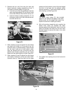
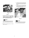
3. Slide the seat rearward, align the front holes and
fasten with the remaining two torx head (or socket
hd.) screws.
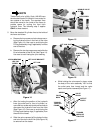
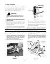
D. INSTALL THE NEW LIFT HANDLE.
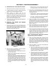
1. From under the left fender, note the direction of the
hex cap screw and lock nut in the existing handle
clamp (See Figure 44).
Figure 44
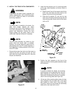
2. In the same direction as the existing clamp, install
the hex cap screw (B) and hex insert lock nut (D)
in the handle clamp (16). Do not tighten the
fasteners completely.
3. With the notch of the clamp facing forward, insert
the new handle (14) into the upper hole from the
left side of the clamp (Refer to Figure 44).
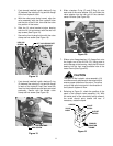
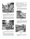
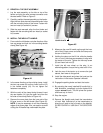
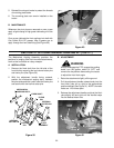
4. Remove the cover plate from the inner slot of the
lift lever cover on the left fender (See Figure 45).
NOTE: It may be necessary to cut the connecting
edges of the cover plate. If so, use caution to avoid
cutting the lift handle flap underneath the plate.
Figure 45
5. Maneuver the new lift handle up through the inner
slot of the lift lever cover and slide the clamp onto
the arm of the lift link.
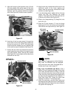
6. Holding the clamp on the lift link, slide the handle
into, or out of, the clamp as necessary to align with
the center of the slot. Tighten the hex cap screw
(B) and insert lock nut (D).
7. Install the left rear wheel on the axle. In an
alternating pattern, torque the lug nuts to 60 ft. lbs.
8. Jack the rear of the tractor up to remove the jack
stands, then lower to the ground.
9. Install the side panels and close the hood per the
instructions in the tractor Operator’s Manual.
10. Engage the parking brake and start the tractor.
11. By actuating the newly installed lift handle fully in
both directions, completely cycle the hydraulic lift
system several times. This will prime the system
and force any air from it.
12. Stop the engine.
13. Remove the dipstick and check the transmission
oil level. Add sufficient oil to the transmission to
bring the oil level to the full mark on the dipstick.
DO NOT OVERFILL. USE ONLY THE SPECIFIED
OIL
LIFT LINK
HANDLE CLAMP
STANDARD LIFT HANDLE
HEX CAP SCREW
NOTCH IN
CLAMP
COVER PLATE
LIFT
HANDLE
FLAP
HANDLE SLOT
(AUX. VALVE #1)
LIFT
LEVER
COVER