


13
Figure 25
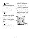
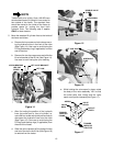
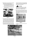
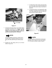
18. Mfg. Code 1D178G20023 and After. If not
already installed, install a backup O-ring (P)
between the existing O-ring and the flange of the
hydro return hose. Insert the hydro return hose into
the rear port of the new valve and secure with the
previously removed valve clamp and hex screw.
Figure 26
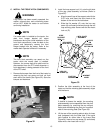
B. INSTALL THE HYDRAULIC TUBES AND
COUPLING ASSEMBLIES.
NOTE
Early production tractors were built with
running board mounting brackets welded to the
frame, while later units have bolt up brackets.
Note which bracket is used on the tractor to
determine which fitting bulkhead will be used.
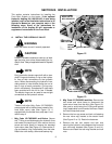
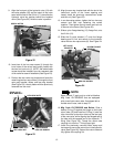
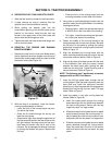
1. Tractors With Welded Frame Brackets. Install
the fitting bulkhead (8) on the LH frame mounting
bracket using the two hex cap screws (C) and hex
insert lock nuts (D) as shown in Figure 27.
Figure 27
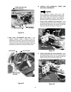
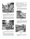
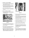
2. Tractors With Bolt Up Frame Brackets. Install
the fitting bulkhead (22) on the LH frame mounting
bracket using the two hex cap screws (C) and hex
insert lock nuts (D) as shown in Figure 28.
Figure 28
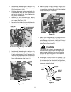
HYDRO RETURN TUBE
(AUX. VALVE #1)
O-RING
COUPLING NUT
HYDRAULIC
‘T’ FITTING
BACKUP
RING
VALVE CLAMP
HEX SCREW
RETURN TUBE
OR HOSE
WELDED FRAME
MOUNTING
BRACKET
HEX CAP
SCREWS
FITTING
BULKHEAD
HEX INSERT
LOCK NUTS
BOLTED FRAME
MTG. BRACKET
HEX CAP
SCREW
FITTING
BULKHEAD
HEX LOCK NUTS
(NOT SEEN)