


19
SECTION IV. TRACTOR REASSEMBLY
A. REPOSITION FUEL TANK AND HITCH PLATE.
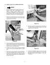
1. Slide the fuel tank fully forward in the frame slots.
2. If used, remove any plug or covering from the
dipstick hole of the transmission housing.
3. While guiding the dipstick tube into the
transmission opening, pivot the hitch plate up into
position on the frame. Install the two hex cap
screws in the upper holes of the hitch plate and
secure with the hex flange lock nuts.
4. Tighten the lower hex cap screws and flange lock
nuts of the hitch plate.
B. REINSTALL THE FENDER AND RUNNING
BOARD ASSEMBLY.
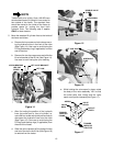
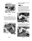
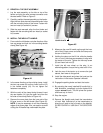
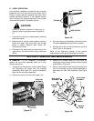
1. Remove the cap from the fuel tank. Make certain
the tail lights and wires are draped over the top of
the fuel tank, and the seat switch wire lead is inside
the tractor frame (See Figure 43).
Figure 43
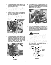
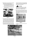
2. With the help of an assistant, install the fender/
running board assembly as follows:
• Lower the front of the running board into posi-
tion above the frame.
• Guide the lift handle through the slot as you
lower the rear fender.
• Route the tail light wires along the upper/rear of
the fuel tank and position the rear fender so the
tail light reflector housings clear the fuel tank,
then lower the fender over the fill neck of the
fuel tank. Do not damage the reflector housings
by forcing the fenders into place. Replace the
fuel cap.
• Press the front of the running board onto the
mounting brackets on each side of the frame.
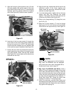
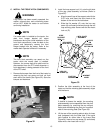
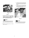
3. Using care to avoid dislodging the bulbs from the
sockets, install the tail light sockets in the reflector
housings as follows:
• Reverse Lights - Install the light sockets having
a WHITE wire in the inner hole of the housing
• Tail Lights - Install the remaining two light sock-
ets in the outer holes of the housing.
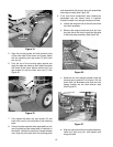
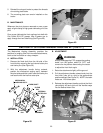
4. Fasten the middle of the running boards to the
frame brackets with the two hex screws. Reinstall
the RH and LH foot pads by pulling the locking
projections through the running board and fender.
Refer to Figure 10.
5. Align the bulkhead and running board with the
frame mounting brackets and secure with the two
hex screws removed earlier. Refer to Figure 8.
6. Align the four tabs of the dash screen with the slots
in the bulkhead, then slide the screen forward
beneath the dash panel while guiding the tabs
under the four wing nuts. Tighten the wing nuts to
secure the screen. Refer to Figure 8.
NOTE: The following step 7 applies only to tractors
equipped with the Diff-Lock feature.
7. Insert the diff-lock pedal down through the left
running board. Slide the pedal w/bearing onto the
pivot shaft and install the previously removed
retaining ring. Align the pedal with the engagement
bracket and secure with the hex wash. hd. tapp
screw. Refer to Figure 7.
8. Install the pedals in the right running board as
follows (Refer to Figure 6):
a. Insert the brake pedal through the running
board and align with the brake lever beneath
the right running board. Secure with the two
longer hex wash. hd. tapp screws.
b. Slide the forward control pedal (arrow on pedal
points forward) through the running board. In-
sert the pedal tab in the slot of the control lever
and secure with the hex wash. hd. tapp screw.
c. Slide the reverse control pedal (arrow on pedal
points rearward) through the running board.
Insert the pedal tab in the slot of the reverse
shaft and secure with the hex wash. hd. tapp
screw.
TAIL LIGHT
WIRES
SEAT SWITCH
WIRE LEAD