


8
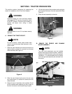
WARNING
Use care when handling the fender and running
board assembly. The edges could cause cuts to
the skin.
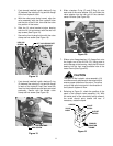
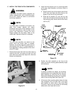
9. With the help of an assistant, lift the front of the
running board off the frame brackets, then raise
the rear fender over the neck of the fuel tank and
the lift handle to remove the fender assembly.
10. Reinstall the cap onto the fuel tank.
C. REMOVE THE LEFT REAR WHEEL.
WARNING
Ensure the front wheels are chocked before
raising the rear of the tractor. Use jack stands to
support the tractor; do not work on the tractor
when supported only by the jack.
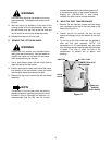
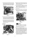
1. Use a jack placed under the rear hitch plate to
raise the rear end of the tractor.
2. Position jack stands under each side of the frame,
just forward of the rear wheels. Lower the tractor
onto the jack stands and remove the jack.
3. Remove the lug nuts to remove the left rear wheel
assembly.
NOTE
The position of the fuel tank limits the working
space available for installing the hydraulic valve
included in this kit. Although not required, it is
recommended that the fuel tank be moved
rearward as described in the following section D
to increase the space. If the optional Hydraulic
Angling Kit (190-288-100) is also being
installed, the tank must be moved rearward.
D. MOVE THE FUEL TANK REARWARD.
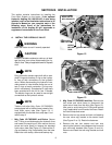
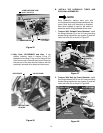
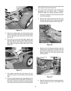
1. Remove the two hex cap screws and hex flange
lock nuts securing the top of the hitch plate to the
frame (See Figure 11).
2. Loosen, but do not remove, the two hex cap
screws and flange nuts at the bottom of the hitch
plate
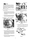
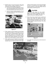
3. Tip the top of the hitch plate back as needed to
slide the fuel tank rearward. NOTE: The
transmission oil fill tube/dipstick may be pulled
from the transmission housing when the hitch plate
is tipped. If so, plug or cover the hole in the
transmission to prevent dirt or debris from
entering.
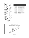
Figure 11
FLANGE LOCK NUTS
(NOT SHOWN)
DIPSTICK
OIL FILL TUBE
HITCH
PLATE
HEX CAP
SCREWS
(BOTH SIDES)