


14
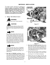
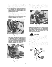
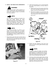
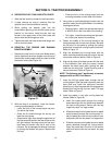
3. Remove the hex nuts from both the male and
female hydraulic coupling assemblies (6 and 7)
and install as follows (Refer to Figure 29):
a. From the front of the fitting bulkhead, insert the
male coupling assembly (6) into the top inside
hole of the bulkhead. Secure with the hex nut.
b. Insert the female coupling assembly (7) into
the bottom inside hole of the bulkhead and se-
cure with the hex nut.
Figure 29
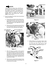
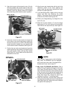
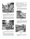
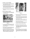
4. Slide a backup O-ring (P) against the tube flange
and install an O-Ring (L) on the end of the ‘up’
hydraulic tube [10 (shorter bends)]. Insert the tube
into the lower outlet port of the hydraulic valve.
Align the flanged front end of the tube with the
tapered male coupling assembly (6) and loosely
fasten with the tube coupling nut (See Figure 30).
5. Slide a backup O-ring (P) against the tube flange
and install an O-Ring (L) on the end of the ‘down’
hydraulic tube (9). Insert the tube into the upper
outlet port of the hydraulic valve. Align the flanged
front end of the tube with the tapered female
coupling assembly (7) and loosely fasten with the
tube coupling nut (See Figure 30).
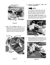
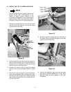
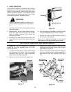
CAUTION
The double valve clamp (21) has rounded
edges on one side and flat edges on the other.
Always place the flat edged side toward the
hydraulic valve when installing the clamp.
6. With its flat surface toward the valve, position the
double valve clamp (21) between the tubes,
squarely against the tube beads. Install a hex cap
screw (K) through the clamp and into the vlave.
Carefully tighten to secure the tubes in the valve
(See Figure 31).
Figure 31
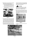
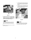
7. Fully tighten the coupling nuts on the front end of
the tubes.
MALE COUPLING ASS’Y.
FEMALE
COUPLING
ASS’Y.
FITTING
BULKHEAD
HEX NUT
DOUBLE
VALVE
CLAMP
HEX CAP
SCREW
‘UP’ HYDRAULIC TUBE
‘DOWN’ HYDRAULIC TUBE
Figure 30
‘DOWN’
HYDRAULIC TUBE
‘UP’
HYDRAULIC TUBE
FEMALE COUPLING
ASSEMBLY
MALE
COUPLING
ASSEMBLY
TUBE
COUPLING
NUT