


12
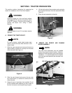
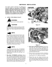
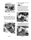
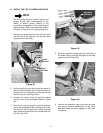
9. Align the front port of the hydraulic valve (19) with
the valve adapter (20) and the notch of the valve
spool with the slot of the lift link (17); then slide the
hydraulic valve into position behind the installed
valve (See Figure 22). Hold the valve in position.
Figure 22
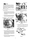
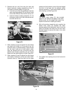
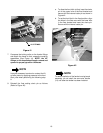
10. Insert two of the hex cap screws (I) through the
inner holes of the valves and loosely fasten with
the two hex lock nuts (J). NOTE: the lower/inside
screw should be inserted from the rearward side
of the valve for ease of installation (See Figure 23).
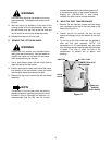
11. Position the rear valve mtg. bracket and insert the
remaining two hex cap screws (I) through the front
valve mtg. bracket, valves, and rear mtg. bracket
(See Figure 23). Loosely fasten with the previously
removed hex lock nuts.
Figure 23
12. Align the rear mtg. bracket hole with the slot in the
lower/front corner of the frame opening and
loosely install the previously removed hex screw
and lock nut (See Figure 23).
13. In an alternating pattern, tighten the four hex cap
screws and lock nuts fastening the valves
together. Then tighten the hex screw and lock nut
to secure to the frame (See Figures 23).
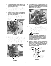
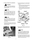
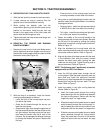
14. Slide a nylon flange bearing (13), flange first, onto
the lift link (15).
15. Slide the lift valve bracket (17) onto the flange
bearing and lift link, and secure to the hydraulic
valve with two hex cap screws (K). See Figure 24.
Figure 24
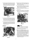
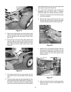
NOTE
Steps 16 and 17 apply only to units built before
Mfg. Code 1D178G20023 that are equipped
with a hard hydro return tube. If equipped with a
flexible return hose, refer to step 18.
16. Mfg. Code 1D178G20022 and Before. Slide a
backup O-ring (P) against the flange on the hydro
return tube (18) and install an O-Ring (L) onto the
tube. Insert the hydro return tube into the rear port
of the new valve, while aligning the flanged end of
the tube with the tapered end of the hydraulic ‘T’
fitting (See Figure 25). Thread the return tube
coupling nut onto the ‘T’ fitting finger tight.
17. Install the previously removed valve clamp and
hex screw to secure the return tube in the hydraulic
valve (See Figure 26). Support the return tube and
fully tighten the coupling nut .
LIFT LINK SLOT
SPOOL NOTCH
REAR VALVE
MTG. BRACKET
HEX LOCK NUTS
HEX
SCREW
HEX LOCK NUT
LOWER/INSIDE
HEX CAP SCREW
FRAME SLOT
HEX CAP SCREW
NYLON FLANGE
BEARING
LIFT VALVE
BRACKET