


11
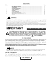
f. If not already installed, install a backup O-ring
(P) between the existing O-ring and the flange
of the front hydraulic tube.
g. With the outlet ports facing inward, align the
valve assembly with the front hydraulic tube
and the slot ot the lift link, then slide the valve
into position in the tractor.
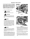
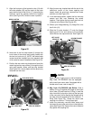
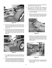
h. Slide the lift valve bracket w/nylon bearing
onto the lift link and secure with the two hex
cap screws (See Figure 18).
i. Secure the front hydraulic tube with the valve
clamp and hex screw (See Figure 18).
Figure 18
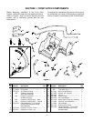
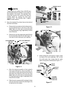
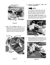
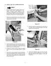
j. If not already installed, install a backup O-ring
(P) between the existing O-ring and the flange
on each of the hydraulic lines, then insert the
lines into their respective outlet ports as noted
previously. Secure with the double valve
clamp and hex screw (See Figure 19).
Figure 19
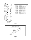
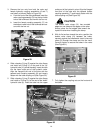
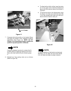
6. Slide a backup O-ring (P) and O-Ring (L) onto
each end of the valve adapter (20), and insert the
valve adapter into the rear port of the standard
center lift valve (See Figure 20).
Figure 20
7. Slide a nylon flange bearing (13), flange first, onto
the longer arm of the lift link (15). Using care to
avoid damage to the bearing, insert the lift link and
bearing into the front most available hole of the
tractor frame (See Figure 20).
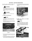
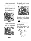
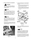
CAUTION
The spool of the hydraulic valve assembly (19)
must be correctly positioned in the valve body to
ensure proper operation of the valve. The arrow
on top of the spool must point in the direction of
the hydraulic system oil flow.
8. Referring to Figure 21, check the position of the
spool in the hydraulic valve assembly (19). With
the outlet ports of the valve body facing outward,
the arrow should point toward the rear. If
necessary, rotate the spool.
Figure 21
LIFT VALVE BRACKET
HEX CAP
SCREW
LIFT
LINK
HEX
SCREW
VALVE
CLAMP
NYLON BEARING
DOUBLE
VALVE CLAMP
HEX SCREW
VALVE
ADAPTER
LIFT LINK
NYLON
FLANGE
BEARING
O-RING
BACKUP RING
ARROW
VALVE
SPOOL
OUTLET
PORTS
VALVE
BODY
TOWARD
TRACTOR
FRAME